Wire electric discharge machine
a wire electric discharge machine and wire technology, applied in the direction of electric circuits, power source circuits, manufacturing tools, etc., can solve the problems of increasing current fed from the other side, affecting the flow rate of wires, and affecting the quality of wires, so as to reduce the number of components, reduce the cost, and facilitate the flow ratio
- Summary
- Abstract
- Description
- Claims
- Application Information
AI Technical Summary
Benefits of technology
Problems solved by technology
Method used
Image
Examples
first embodiment
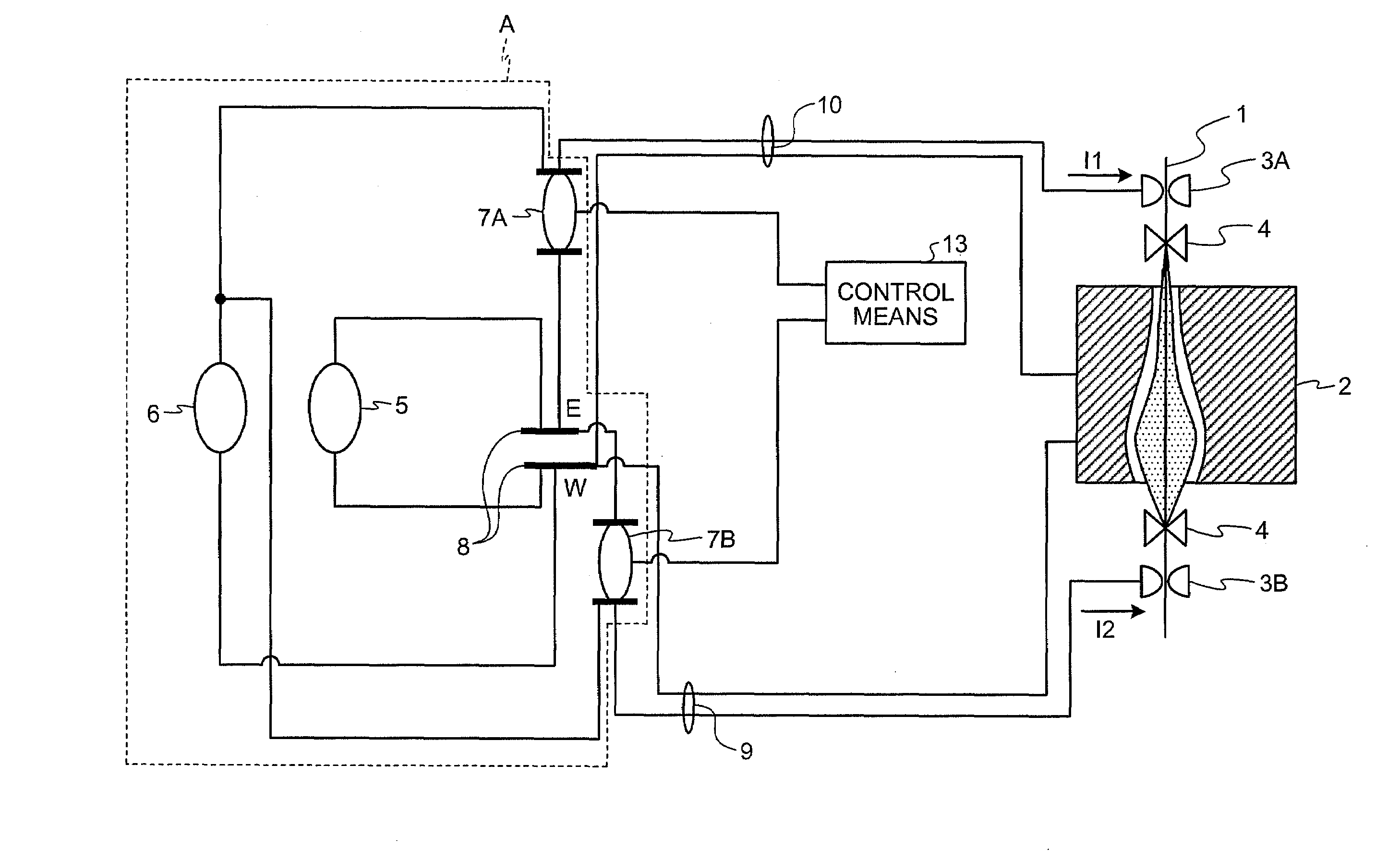
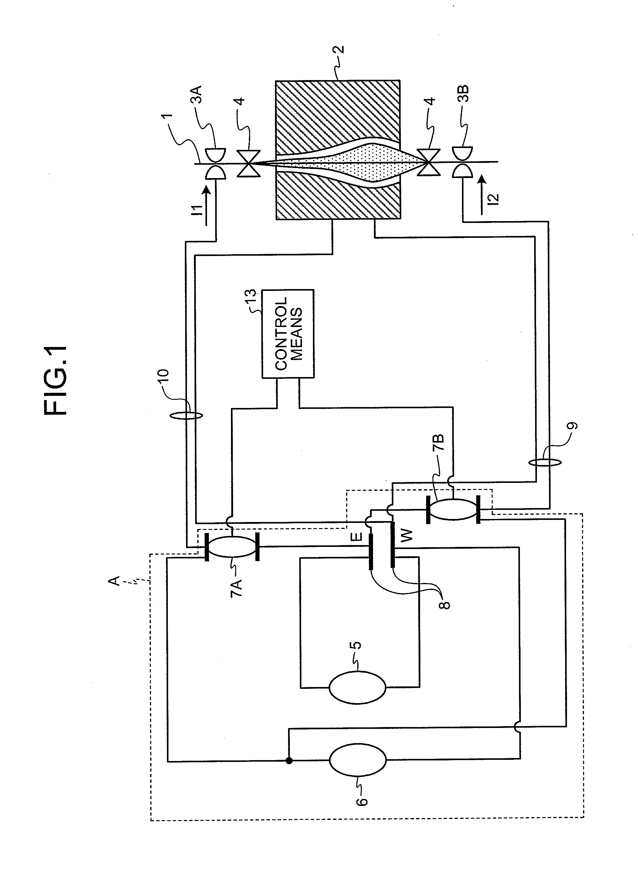
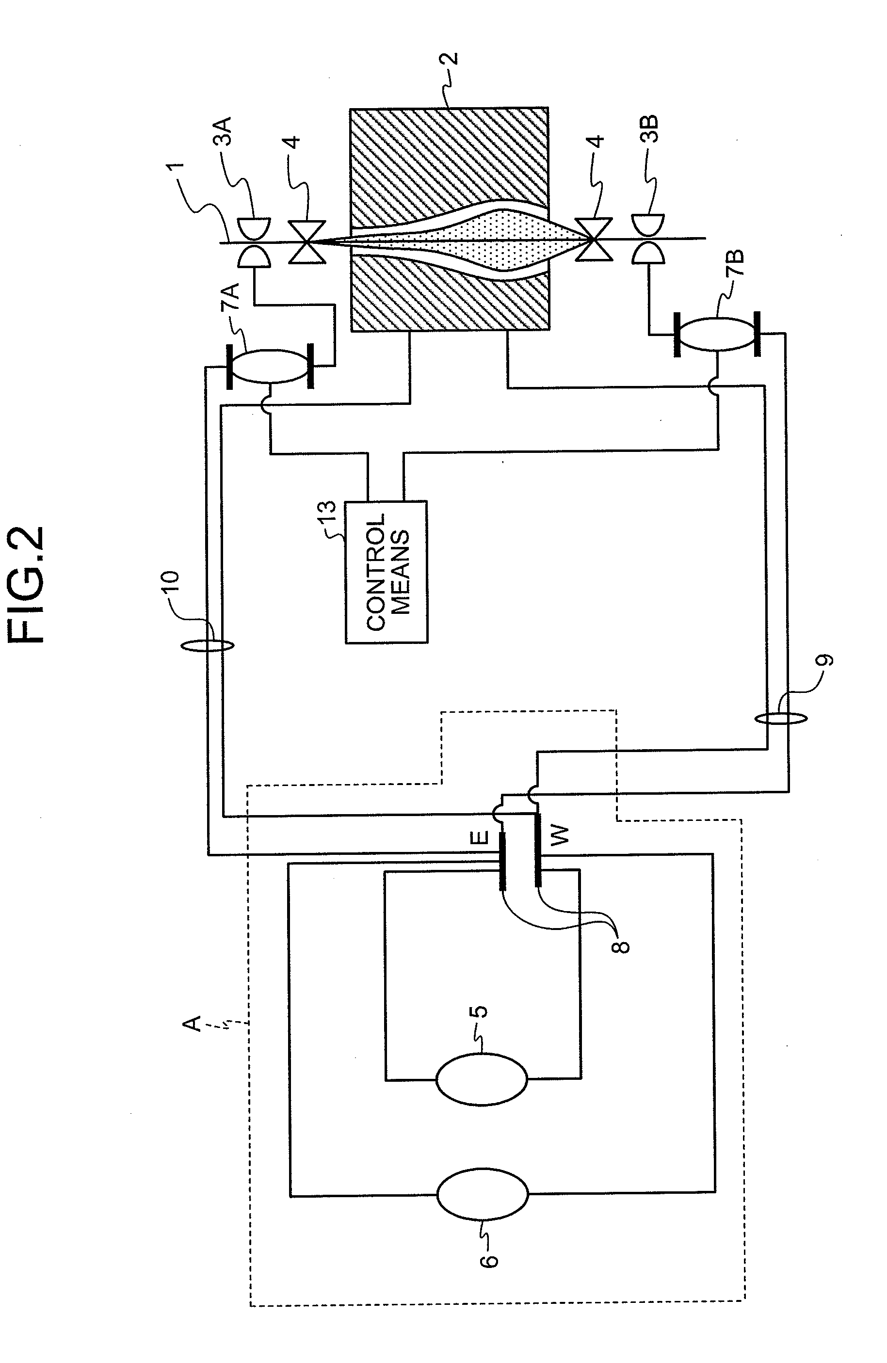
[0047]FIG. 1 is a schematic diagram of main elements of a wire electric discharge machine according to a first embodiment of the present invention. The wire electric discharge machine shown in FIG. 1 generates an electric discharge between a wire electrode 1 and a workpiece 2 by application of a voltage thereby machining. The wire electric discharge machine includes the wire electrode 1, an upper power feed contact (a first power feed contact) 3A, and a lower power feed contact (a second power feed contact) 3B. The wire electrode 1 extends in an up-and-down direction, and moves in the up-and-down direction by being guided by wire guides 4 on the upper and lower sides of the workpiece 2. The upper power feed contact 3A and the lower power feed contact 3B are respectively provided on the upper and lower sides of the workpiece 2. The upper power feed contact 3A and the lower power feed contact 3B respectively feed to the wire electrode 1 by having contact with the wire electrode 1.
[004...
second embodiment
[0071]FIG. 6 is a schematic diagram of main elements of a wire electric discharge machine according to a second embodiment of the present invention. In the second embodiment, the impedance switching circuits 7A and 7B are inserted in the machining-current loop of the sub discharge power supply 6. In the present embodiment, a machining shape in the through-thickness direction cannot be controlled in rough machining. Therefore, it may cause a dimensional difference in the through-thickness direction as in the conventional technology. However, in the present embodiment, a dimension error occurred in the rough machining can be corrected in finish machining.
[0072]A basic configuration shown in FIG. 6 is almost identical to that for the first embodiment. The sub discharge power supply 6 is configured to be connected to the upper power feed contact 3A and the lower power feed contact 3B via an upper sub-feeder line 11 and a lower sub-feeder line 12 before the interelectrode. Specifically, ...
third embodiment
[0076]FIG. 7 is a schematic diagram of main elements of a wire electric discharge machine according to a third embodiment of the present invention. In the first embodiment, there is provided one number of the main discharge power supply 5. In the present embodiment, there are provided two main discharge power supplies, i.e., a main discharge power supply (a first machining power supply) 5A connecting to the upper power feed contact 3A and a main discharge power supply (a second machining power supply) 5B connecting to the lower power feed contact 3B. Output terminals of the main discharge power supplies 5A and 5B are denoted by 8A and 8B, respectively. The W-side of the output terminal 8A is connected to the W-side of the output terminal 8B. The sub discharge power supply 6 is connected in parallel to each of the main discharge power supplies 5A and 5B. The output terminal 8A is connected to the upper power feed contact 3A via the feeder line 10, and the output terminal 8B is connec...
PUM
| Property | Measurement | Unit |
|---|---|---|
| Ratio | aaaaa | aaaaa |
| Electric potential / voltage | aaaaa | aaaaa |
| Electric impedance | aaaaa | aaaaa |
Abstract
Description
Claims
Application Information
 - R&D
- Intellectual Property
- Life Sciences
- Materials
- Tech Scout
- Unparalleled Data Quality
- Higher Quality Content
- 60% Fewer Hallucinations
Browse by: Latest US Patents, China's latest patents, Technical Efficacy Thesaurus, Application Domain, Technology Topic, Popular Technical Reports.
© 2025 PatSnap. All rights reserved.Legal|Privacy policy|Modern Slavery Act Transparency Statement|Sitemap|About US| Contact US: help@patsnap.com


