Permanent magnet synchronous machine with shell magnets

Inactive Publication Date: 2009-12-24
SIEMENS AG
View PDF7 Cites 36 Cited by
  • Summary
  • Abstract
  • Description
  • Claims
  • Application Information

AI Technical Summary

Benefits of technology

[0017]By addressing these causes of torque ripple, measures implemented in accordance with the present invention each further reduce torque ripple without having to additionally modify the stator and/or the rotor by inclining the slots and/or the permanent magnets or by staggering them.
[0018]In particular, considerable reduction in the torque ripple is achieved by the quasi

Problems solved by technology

Permanent-magnet synchronous machines often exhibit torque ripple during operation, which generally results in undesirable harmonics from the interaction between the slot system and the pole formation, which harmonics occur as cogging torques (reluctance moments

Method used


Image

  • Permanent magnet synchronous machine with shell magnets
  • Permanent magnet synchronous machine with shell magnets
  • Permanent magnet synchronous machine with shell magnets

Examples


Embodiment Construction

[0030]Throughout all the figures, same or corresponding elements may generally be indicated by same reference numerals. These depicted embodiments are to be understood as illustrative of the invention and not as limiting in any way. It should also be understood that the figures are not necessarily to scale and that the embodiments are sometimes illustrated by graphic symbols, phantom lines, diagrammatic representations and fragmentary views. In certain instances, details which are not necessary for an understanding of the present invention or which render other details difficult to perceive may have been omitted.

[0031]The invention is also applicable to combination drives in which a rotating electric motor and a cylindrical linear motor jointly drive a shaft and move axially. Such a combination drive is described, for example, in German Offenlegungsschrift DE 10 2004 056 212 A1. The content of that German laid-open application is included herein by reference.

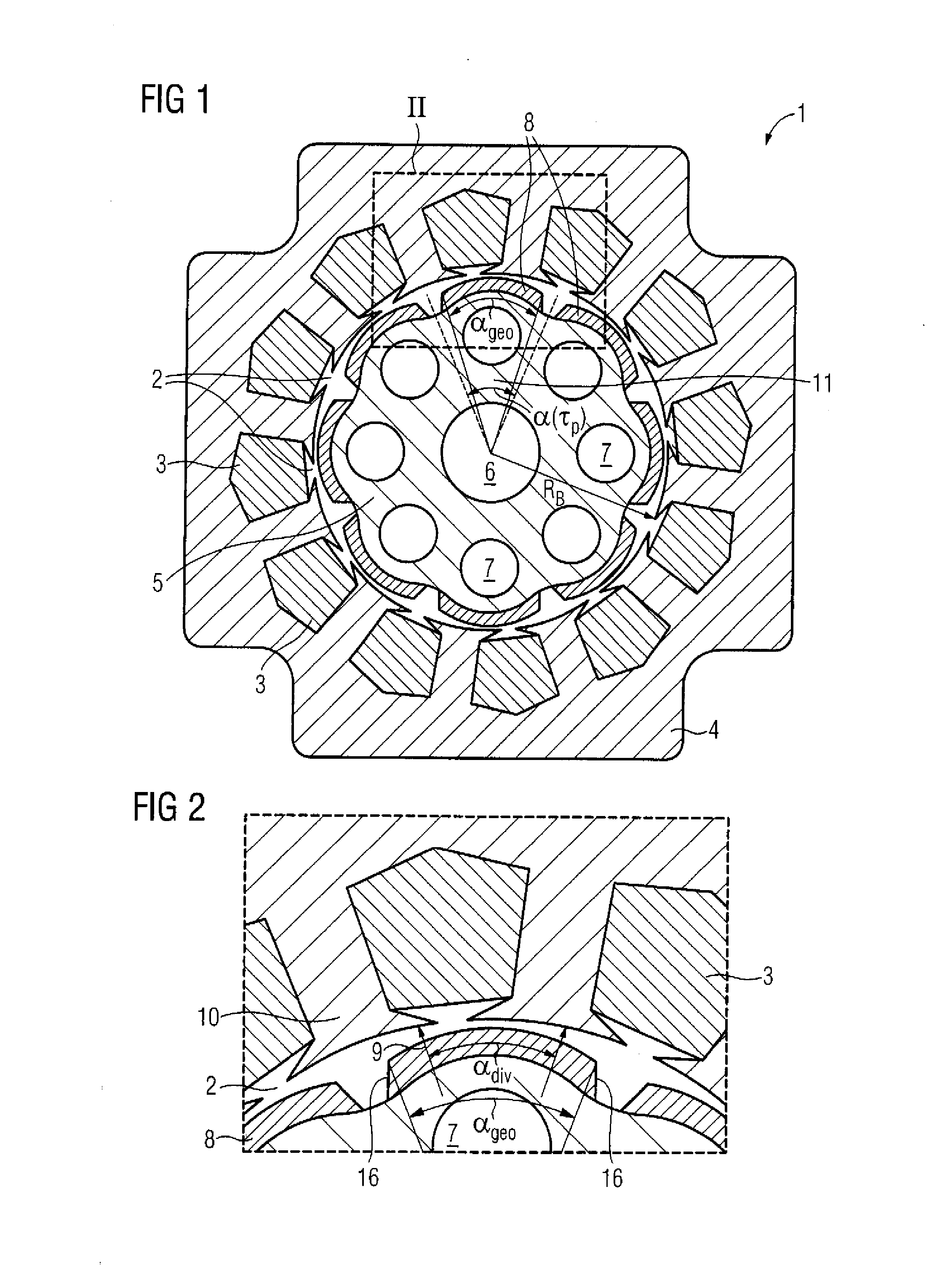
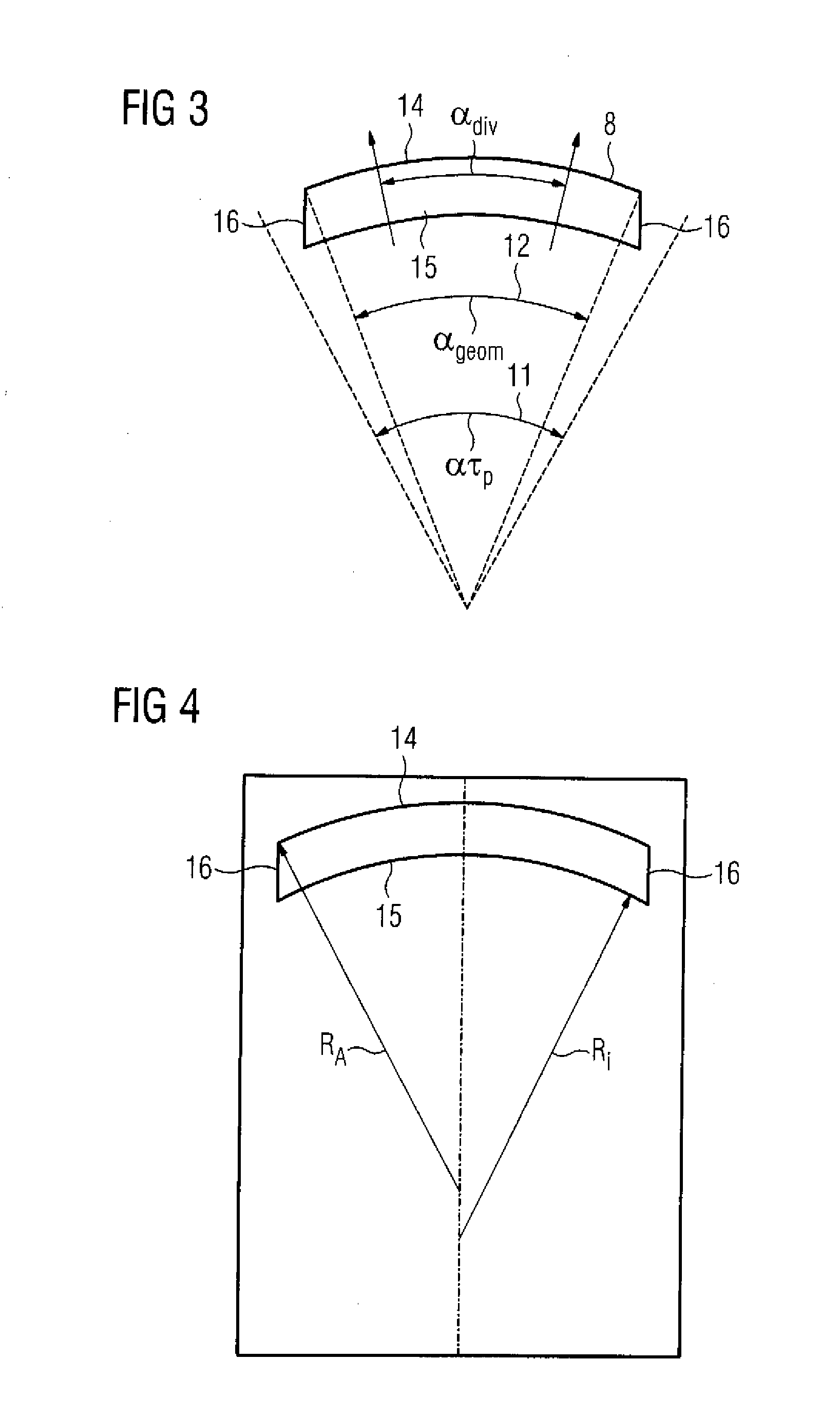
[0032]Turning now to the...


PUM


Abstract

A permanent-magnet synchronous machine includes a stator that has slots and a rotor that has permanent magnets which form magnet poles. The permanent magnets are shell magnets having two curved surfaces. Each shell magnet covers a predetermined part of a magnet pole. The external radius of the shell magnets is less than 0.6 times the radius of the stator bore. Each shell magnet has a quasi-radial magnetic preferred direction that is directed substantially perpendicular to its outer surface.

Description

CROSS-REFERENCES TO RELATED APPLICATIONS[0001]This application claims the priority of European Patent Application, Serial No. 07024405, filed Dec. 17, 2007, pursuant to 35 U.S.C. 119(a)-(d), the content of which is incorporated herein by reference in its entirety as if fully set forth herein.BACKGROUND OF THE INVENTION[0002]The present invention relates, in general, to a permanent-magnet synchronous machine.[0003]Nothing in the following discussion of the state of the art is to be construed as an admission of prior art.[0004]Permanent-magnet synchronous machines often exhibit torque ripple during operation, which generally results in undesirable harmonics from the interaction between the slot system and the pole formation, which harmonics occur as cogging torques (reluctance moments) and result in harmonics in the induced voltage caused by the excitation field.[0005]Various structural suppression means for reducing this phenomenon in dynamo-electric machines are known. For example, ...

Claims


Application Information

Patent Timeline
IPC IPC(8): H02K1/27
CPCH02K29/03H02K1/278H02K1/2781
Inventor VOLLMER, ROLF
Owner SIEMENS AG
Why Eureka
Try Eureka