Brightness-adjustable LED driving circuit

Active Publication Date: 2009-12-24
DELTA ELECTRONICS INC
View PDF5 Cites 70 Cited by
  • Summary
  • Abstract
  • Description
  • Claims
  • Application Information

AI Technical Summary

Benefits of technology

[0008]It is an object of the present invention to provide a brightness-adjustable LED driving circuit cooperating with a brightness-adjustable circuit

Problems solved by technology

If the LED driving circuit and the brightness-adjustable circuit are simultaneously used, the LED possibly flashes or the LED driving circuit or the brightness-adjustable circuit is readily burnt out because the LED driving circuit can only receive power signals with constant on phase or

Method used


Image

  • Brightness-adjustable LED driving circuit
  • Brightness-adjustable LED driving circuit
  • Brightness-adjustable LED driving circuit

Examples


Embodiment Construction

[0021]The present invention will now be described more specifically with reference to the following embodiments. It is to be noted that the following descriptions of preferred embodiments of this invention are presented herein for purpose of illustration and description only. It is not intended to be exhaustive or to be limited to the precise form disclosed.

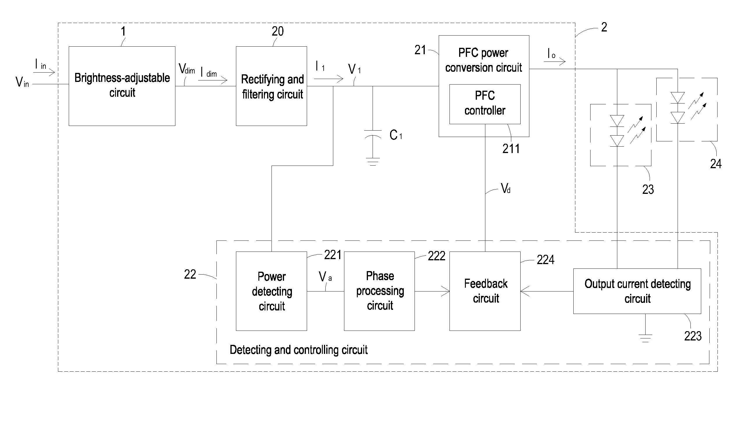
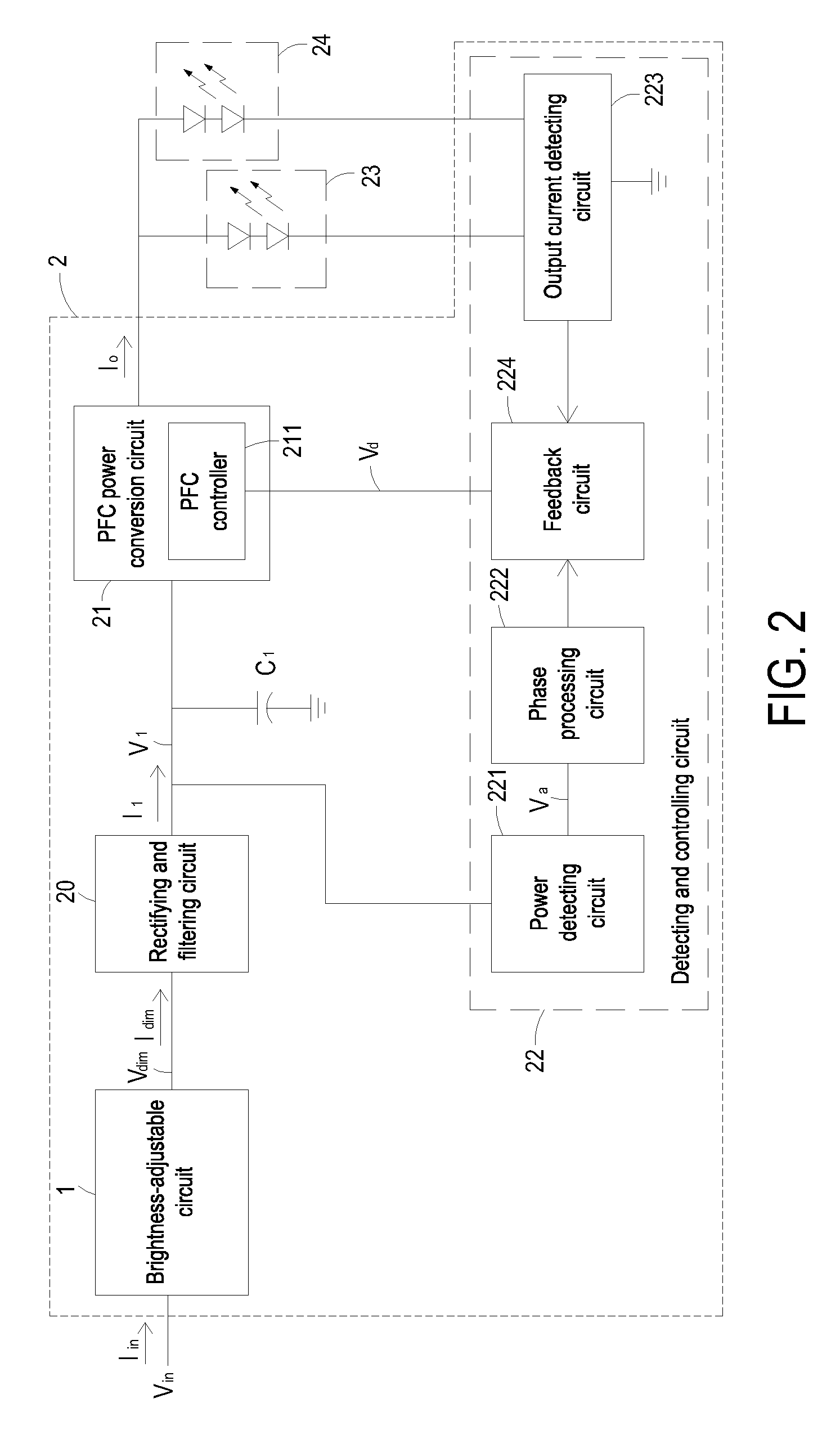
[0022]The brightness-adjustable LED driving circuit of the present invention can be used for driving one or more LED strings. Each LED string includes one or more LEDs. For clarification, two LED strings of each having two LEDs are shown in the drawings.

[0023]FIG. 2 is a schematic circuit block diagram illustrating a brightness-adjustable LED driving circuit according to a preferred embodiment of the present invention. As shown in FIG. 2, the brightness-adjustable LED driving circuit 2 of the present invention principally comprises a brightness-adjustable circuit 1, a rectifying and filtering circuit 20, a power factor correction...


PUM


Abstract

A brightness-adjustable LED driving circuit includes a rectifying and filtering circuit, a power factor correction power conversion circuit, and a detecting and controlling circuit. The rectifying and filtering circuit is used for filtering and rectifying a brightness adjusting voltage into a first DC voltage. The power factor correction power conversion circuit is electrically connected to the rectifying and filtering circuit and at least one LED string for generating an output current required for powering the at least one LED string. The detecting and controlling circuit detects phase data of the brightness adjusting voltage and the output current generated by the power factor correction power conversion circuit. The detecting and controlling circuit generates a control signal to the power factor correction controller according to the phase data of the brightness adjusting voltage, so that the magnitude of the output current is changed according to the phase data of the brightness adjusting voltage.

Description

FIELD OF THE INVENTION[0001]The present invention relates to a LED driving circuit, and more particularly to a brightness-adjustable LED driving circuit.BACKGROUND OF THE INVENTION[0002]Incandescent lamps such as tungsten filament lamps or halogen lamps are widely used as sources of artificial light. In the early stage, incandescent lamps are used for simply providing a bright place. With diversified living attitudes, incandescent lamps having difference brightness are developed. For adjusting brightness of respective incandescent lamp, a brightness-adjustable circuit is used to drive the incandescent lamp and control the brightness of the incandescent lamp.[0003]FIG. 1 is a schematic circuit diagram illustrating a brightness-adjustable circuit for a conventional incandescent lamp. As shown in FIG. 1, the brightness-adjustable circuit 1 includes a switch element 11 and a triggering circuit 12. The switch element 11 is for example a solid semiconductor component such as a silicon-con...

Claims


Application Information

Patent Timeline
IPC IPC(8): H05B41/36
CPCH05B33/0845H05B33/0815H05B45/10H05B45/385
Inventor YAN, SHANG-JINHUANG, CHUNG-TSAILEE, PO-YI
Owner DELTA ELECTRONICS INC
Why Eureka
Try Eureka