Heat dissipation device of vehicle lamp and interposing element thereof

a technology for vehicle lamps and interposing elements, which is applied in the field of vehicle lamps, can solve the problems of inability to efficiently lower the and high heat generated during the operation of the high-power led assembly etc., to achieve the effect of dissipating moisture in the vehicle lamp, avoiding poor performance or being burned out, and suitable working temperatur

Active Publication Date: 2010-12-16
MAN ZAI IND
View PDF1 Cites 29 Cited by
  • Summary
  • Abstract
  • Description
  • Claims
  • Application Information

AI Technical Summary

Benefits of technology

[0012]Through the heat dissipation device, the present invention is characterized in that the heat dissipation device is applied to the vehicle lamp. After the vehicle lamp is turned on, the heat generated when the LED assembly is turned on is dissipated through the heat sink, so that the LED assembly is cooled down. In another aspect, the air feeding fan draws the cold air in the front partition to pass through the air feeding channel and the heat sink, and the hot air then enters the rear partition on the rear end of the vehicle lamp. Further, the back flow fan draws the hot air in the rear partition to the front partition on the front end of the vehicle lamp through the back flow channel. When the vehicle travels, an external air flow blows through the lamp cover of the vehicle lamp, so that the hot air entering the front partition is cooled down by the lamp cover with a relatively low temperature. Through such a circulation of air flow, the LED assembly can maintain a suitable working temperature, and can avoid poor performance or being burned out due to high temperature.
[0013]In addition, when the heat dissipation device of the present invention is applied to the vehicle lamp, the heat dissipation device can provide the circulating air flow between the front partition and the rear partition in the vehicle lamp, so as to dissipate moisture in the vehicle lamp, thereby preventing the moisture from condensing in the lamp cover with the relatively low temperature and resulting in atomization. Under a cold climate, the heat dissipation device guides the hot air in the rear partition to the lamp cover, so as to heat the lamp cover to remove ice frost condensed on the outer surface of the lamp cover.

Problems solved by technology

During operation, the high-power LEDs generate high heat.
However, the conventional LED vehicle lamp structure lacks a suitable heat dissipation mechanism, so the high heat generated during the operation of the high-power LED assembly in the vehicle lamp cannot be lowered efficiently.
Therefore, the high-power LEDs tend to be over-heated and have poor performance or may even be burned out.

Method used


Image

  • Heat dissipation device of vehicle lamp and interposing element thereof
  • Heat dissipation device of vehicle lamp and interposing element thereof
  • Heat dissipation device of vehicle lamp and interposing element thereof

Examples


first embodiment

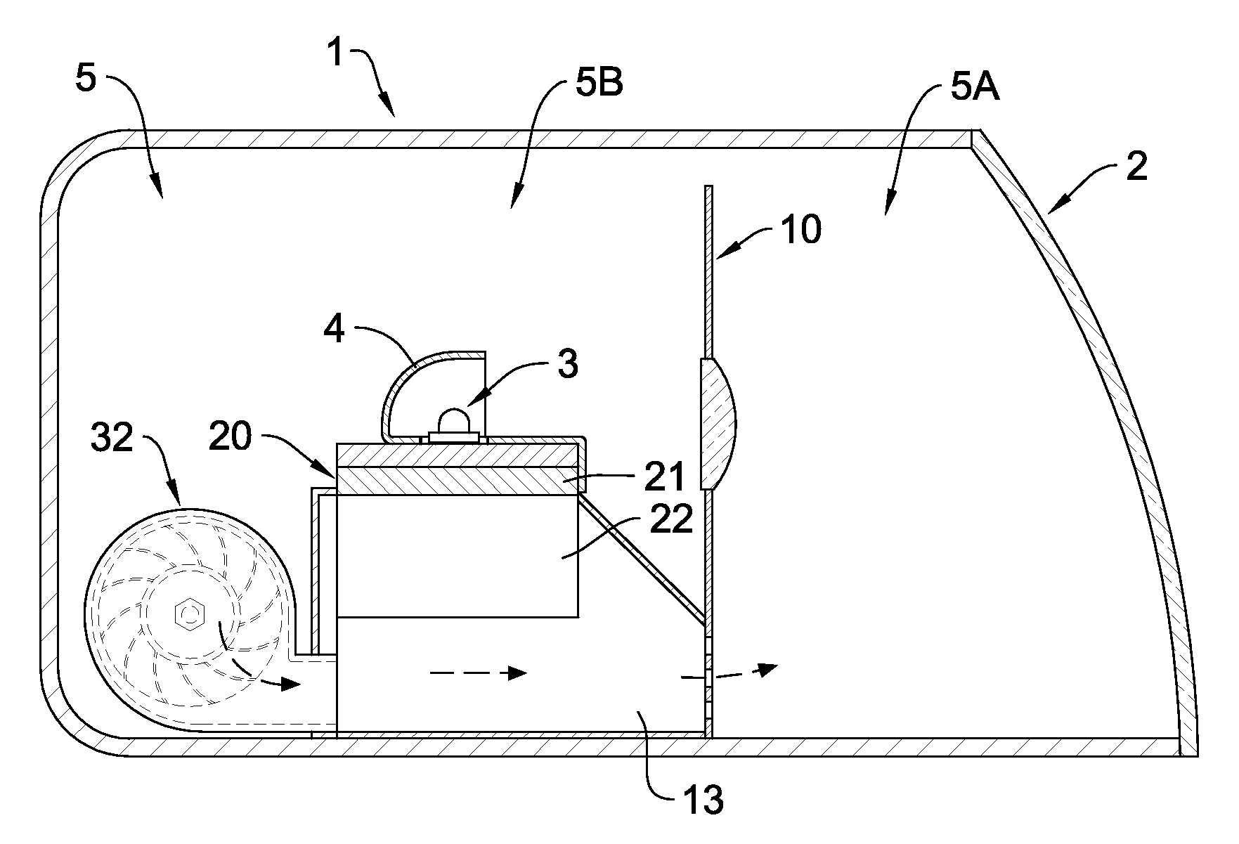
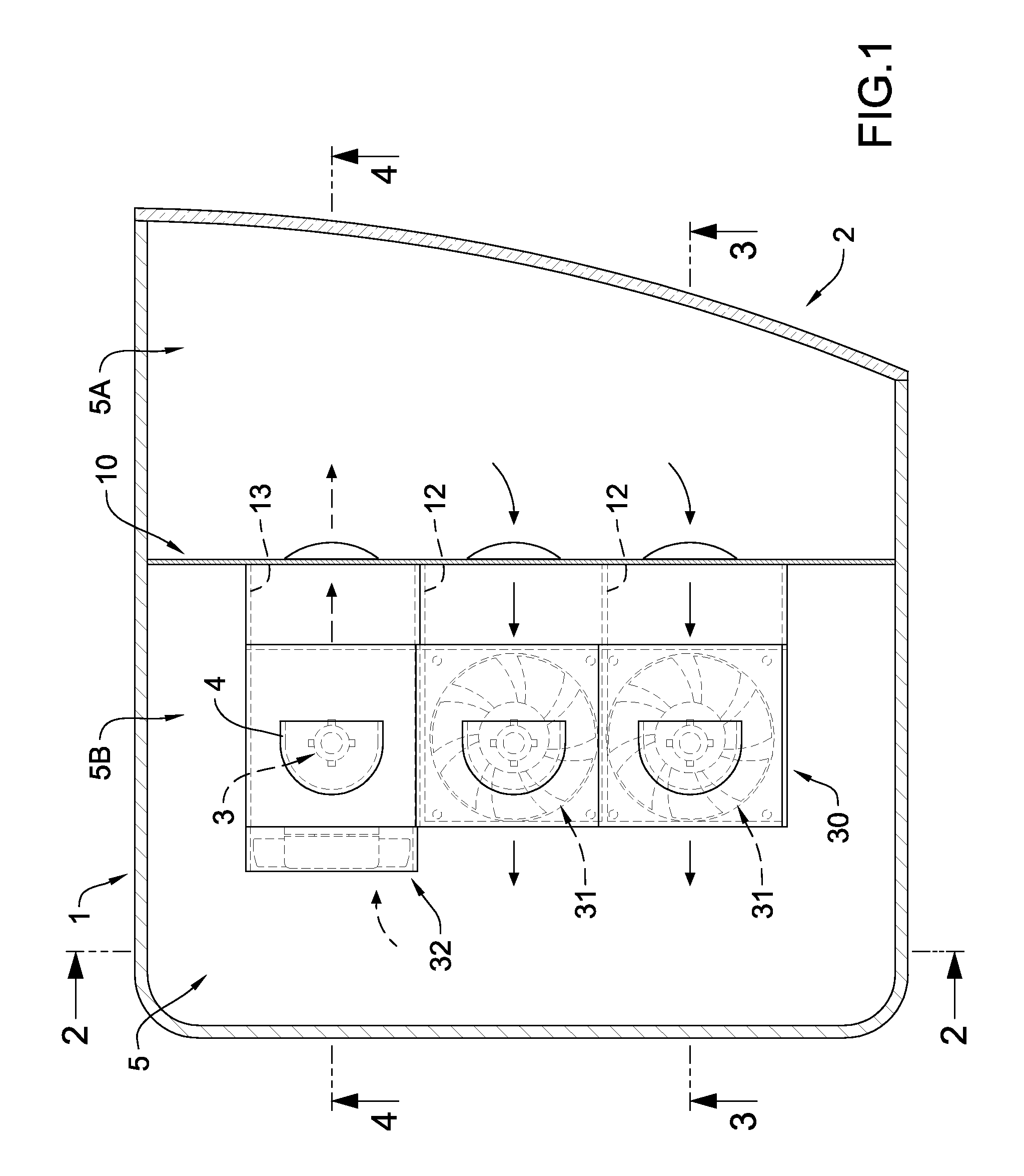
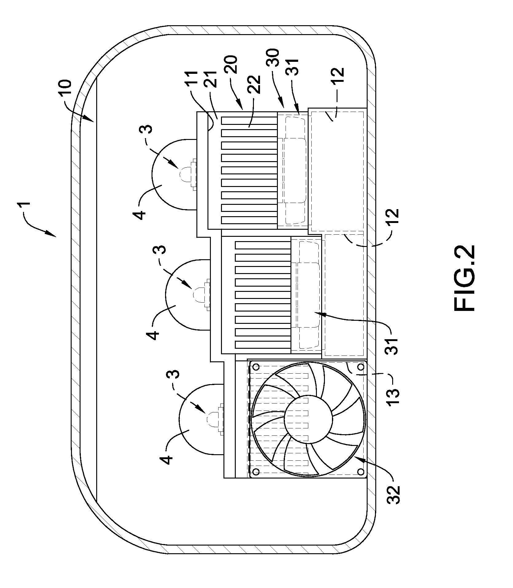
[0025]FIGS. 1 to 4 show operation of a heat dissipation device according to the present invention when applied to an LED vehicle lamp. FIG. 2 is a cross-sectional view taken along line 2-2 in FIG. 1, FIG. 3 is a cross-sectional view taken along line 3-3 in FIG. 1, and FIG. 4 is a cross-sectional view taken along line 4-4 in FIG. 1. As shown in the figures, the vehicle lamp includes a lamp housing 1, a lamp cover 2, at least one LED assembly 3, at least one reflecting element 4, and a heat dissipation device. The lamp cover 2 is assembled on a front end of the lamp housing 1. The internal space of the lamp housing 1 and the lamp cover 2 is formed as a lamp room 5. The LED assembly 3 includes a circuit board and a plurality of high-power LEDs disposed on the circuit board. The LED assembly 3 is disposed in the lamp room 5. The reflecting element 4 is located at a light path of the LED assembly 3, and serves to reflect the light emitted by the LED assembly 3 and make it pass through th...

second embodiment

[0031]FIGS. 5 and 6 show operation of the heat dissipation device according to the present invention when applied to the LED vehicle lamp, in which FIG. 6 is a cross-sectional view taken along line 6-6 in FIG. 5. In this embodiment, a back flow fan 32a may be a radial-flow blower, and is disposed on the rear partition 5B behind the back flow channel 13, so that an outlet of the back flow fan 32a communicates with the rear end of the back flow channel 13, and an inlet of the back flow fan 32a communicates with the rear partition 5B.

third embodiment

[0032]FIGS. 7 to 11 show operation of the heat dissipation device according to the present invention when applied to the LED vehicle lamp. FIG. 8 is a cross-sectional view taken along line 8-8 in FIG. 7, FIG. 9 is a schematic exploded view of FIG. 8, FIG. 10 is a cross-sectional view taken along line 10-10 in FIG. 7, and FIG. 11 is a cross-sectional view taken along line 11-11 in FIG. 7.

[0033]The heat dissipation device of the vehicle lamp in this embodiment is installed in the lamp room 5 of the vehicle lamp, and the heat dissipation device includes an interposing element 60, a first heat sink 71, a second heat sink 72, and a air supply assembly a first air feeding fan 81 and a back flow fan 82.

[0034]The interposing element 60 is used to divide the lamp room 5 into a front partition 5A and a rear partition 5B. The interposing element 60 includes a first accommodating room 14, a second accommodating room 15, a first air feeding channel 16, and a back flow channel 17. The first accom...


PUM


Abstract

A heat dissipation device of a vehicle lamp and an interposing element thereof are provided. The heat dissipation device is installed in a lamp room which is divided by the interposing element into a front partition and a rear partition. A heat sink is installed in the interposing elements. An air feeding fan is disposed in an air feeding channel of the interposing element, for drawing air in the front partition to the rear partition through the air feeding channel. Further, a back flow fan is disposed in the rear partition, for drawing air in the rear partition to the front partition through a back flow channel. Whereby, the air in the front partition is cooled down through an external air flow passing through the lamp cover. Then, the heat sink dissipates heat of the air flow with the relatively low temperature in the front partition to the rear partition.

Description

BACKGROUND OF THE INVENTION[0001]1. Field of the Invention[0002]The present invention relates to a vehicle lamp, and more particularly to a heat dissipation device applied to a light emitting diode LED vehicle lamp and capable of providing an excellent heat dissipation function.[0003]2. Description of the Related Art[0004]With such advantages as low power consumption, long service life, and other excellent functions, LEDs are now widely applied in various light emitting devices to serve as light source. In existing vehicle lamp designs, high-power LEDs have increasingly replaced conventional bulbs as the light source.[0005]In the conventional LED vehicle lamp, a combination of several high-power LEDs is used as a light emitting assembly in order to provide sufficient brightness. During operation, the high-power LEDs generate high heat. The light emitting assembly is installed in a vehicle lamp housing which is disposed on a front end of the vehicle and has a rear end abutting an eng...

Claims


Application Information

Patent Timeline
Patent Type & Authority Applications(United States)
IPC IPC(8): B60Q1/00
CPCF21V29/02F21V29/74F21V29/763F21V29/673F21S45/33F21S41/147F21S45/43F21S45/60F21V29/677F21S41/148F21S41/151F21S45/435
Inventor WAN, CHENG-FENGLIN, HAO-HUIHU, SU-CHENCHEN, CHEN-JUNGHUANG, HUI-FEN
Owner MAN ZAI IND
Why Eureka
Try Eureka