
Method for detecting an identification object in a vehicle

Active Publication Date: 2009-12-24
VALEO SECURITE HABITACLE
View PDF5 Cites 18 Cited by
  • Summary
  • Abstract
  • Description
  • Claims
  • Application Information

AI Technical Summary

Benefits of technology

[0019]Thus, the calibration signal depends on a current measurement which is simple to implement.
[0027]The method includes an additional initial step for writing a fixed threshold value in the identification object. This makes it possible to obtain a fixed reception field from which the identification object can receive signals from the antenna device and communicate with an associated control device.

Problems solved by technology

Such a solution presents the drawback of being difficult to implement.

Method used


Image

  • Method for detecting an identification object in a vehicle
  • Method for detecting an identification object in a vehicle
  • Method for detecting an identification object in a vehicle

Examples


Embodiment Construction

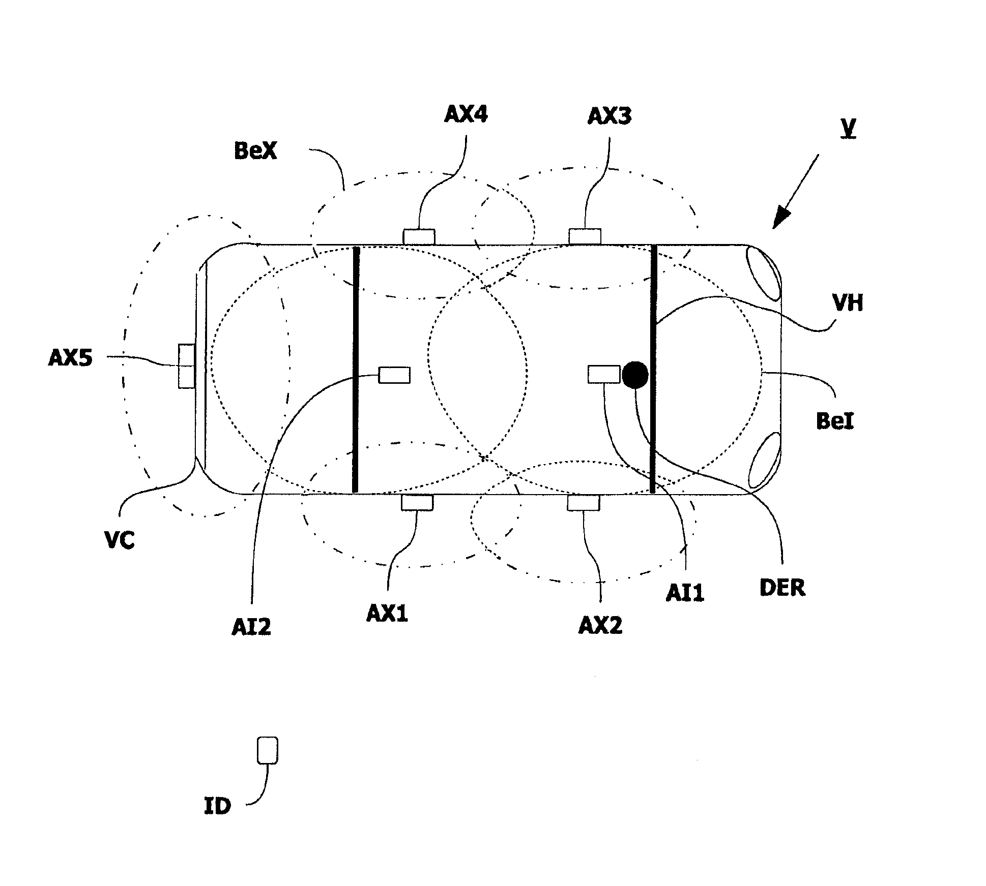
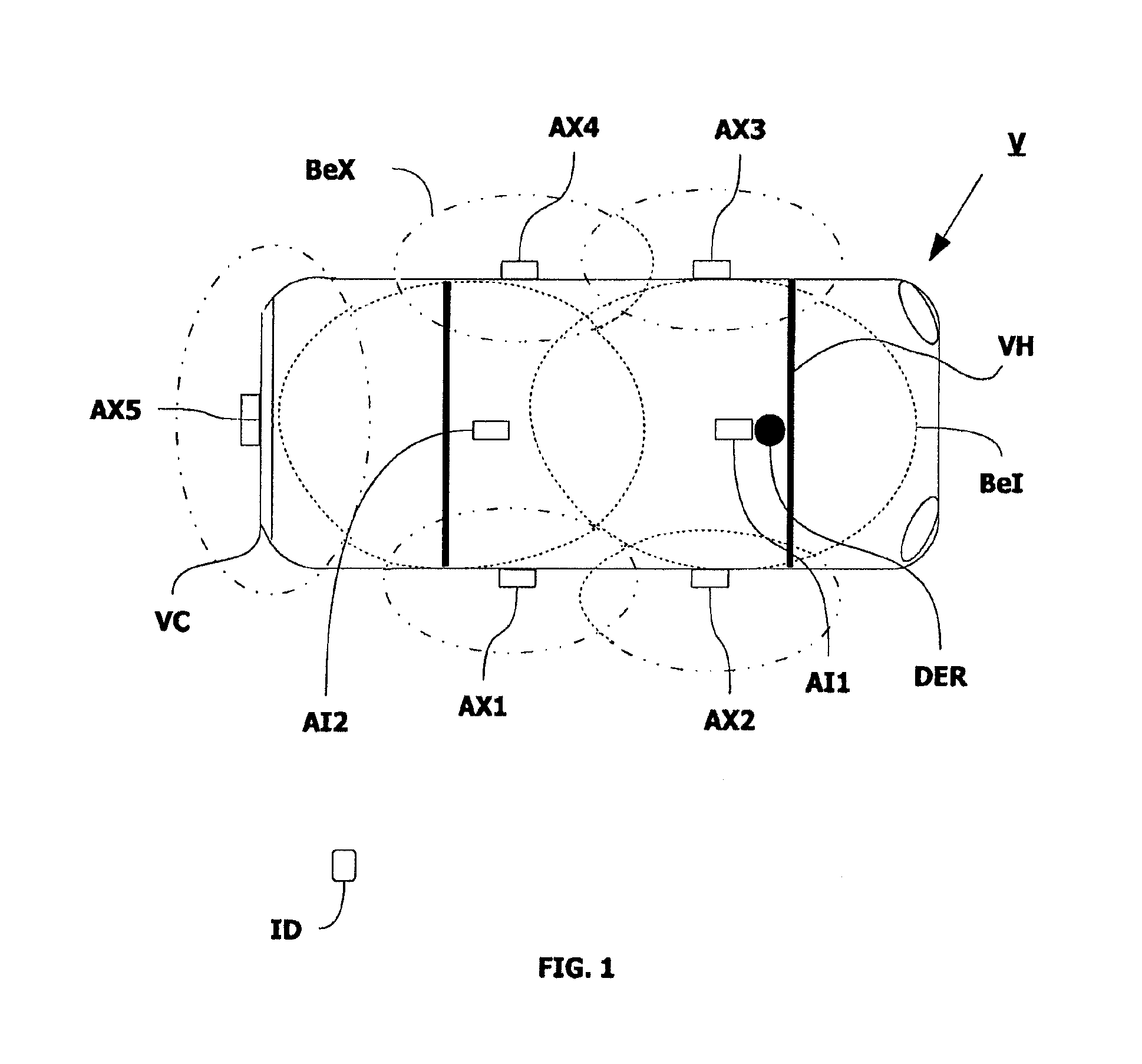
[0063]FIG. 1 represents a vehicle V provided with a transceiver device DER for signals used to control an antenna device A, and the antenna device A comprising, in a nonlimiting example, a plurality of antennas, in this case “external” antennas AX and “internal” antennas AI, all these antennas cooperating with a receiver-emitter ID, the whole forming a detection system described hereinbelow.

[0064]The nonlimiting example of the figure shows five external antennas AX, of which four, AX1, AX2, AX3 and AX4, are located outside the passenger compartment VH of the vehicle V, in this case on handles of the doors, and one AX5 is located in the rear bumper VC of the vehicle. Moreover, two internal antennas AI1, AI2 are located in the passenger compartment VH, in this case at the front and at the rear of the vehicle. Each antenna is fed with low-frequency alternating current by the transceiver device DER and emits a magnetic field Be, denoted BeI for the internal antennas and BeX for the exte...


PUM


Abstract

The invention relates to a method for detecting an identification object in an area (ZO) around an antenna device. The invention is characterised in that it comprises the following steps in which: a calibration signal (S_CAL) is emitted in the direction of the antenna device in order to determine a control power (PR); a functional signal (S_FONC) corresponding to the control power (PR) is emitted in the direction of the antenna device, such that the antenna device emits a pre-determined magnetic field; the magnetic field (Br) received by the identification object, corresponding to the emitted magnetic field, is measured and compared with a nominal magnetic field (B0); and, depending on the result of said comparison, it is determined if the identification object is located inside the area (ZO) around the antenna device. The invention is suitable for motor vehicles.

Description

CROSS REFERENCE TO RELATED APPLICATIONS[0001]The present application is a continuation of PCT / EP2007 / 064428, filed Dec. 21, 2007;which claims priority to FR 0611343, filed Dec. 22, 2006.FIELD OF THE INVENTION[0002]The present invention relates to a method of detecting an identification object in an area around an antenna device and a detection system implementing the detection method.[0003]It is particularly applicable for a motor vehicle fitted with a hands-free detection system.STATE OF THE ART[0004]According to a known state of the art, there is a method of detecting an identification object, such as a badge, which serves as a receiver-emitter for ascertaining whether it is located inside or outside the passenger compartment of the vehicle. If the badge is located inside the vehicle, the user is allowed to start the vehicle.[0005]The detection of the badge is based on a magnetic field emitted from a constant power from a voltage regulation of the antenna device.[0006]Such a solut...

Claims


Application Information

Patent Timeline
IPC IPC(8): G06K7/00
CPCG07C9/00309G07C2209/63G07C2009/00793
Inventor LECONTE, ERICVIOLLEAU, STEPHANE
Owner VALEO SECURITE HABITACLE
Learn More