Tactile sensor using elastomeric imaging

a technology of elastomeric imaging and tactile sensors, applied in the field of tactile sensors, can solve the problem of not being able to achieve all of these goals in a single sensor

Active Publication Date: 2009-12-24
MASSACHUSETTS INST OF TECH
View PDF28 Cites 128 Cited by
  • Summary
  • Abstract
  • Description
  • Claims
  • Application Information

AI Technical Summary

Problems solved by technology

It has been impossible to achieve all of these goals in a single sensor.

Method used


Image

  • Tactile sensor using elastomeric imaging
  • Tactile sensor using elastomeric imaging
  • Tactile sensor using elastomeric imaging

Examples


Embodiment Construction

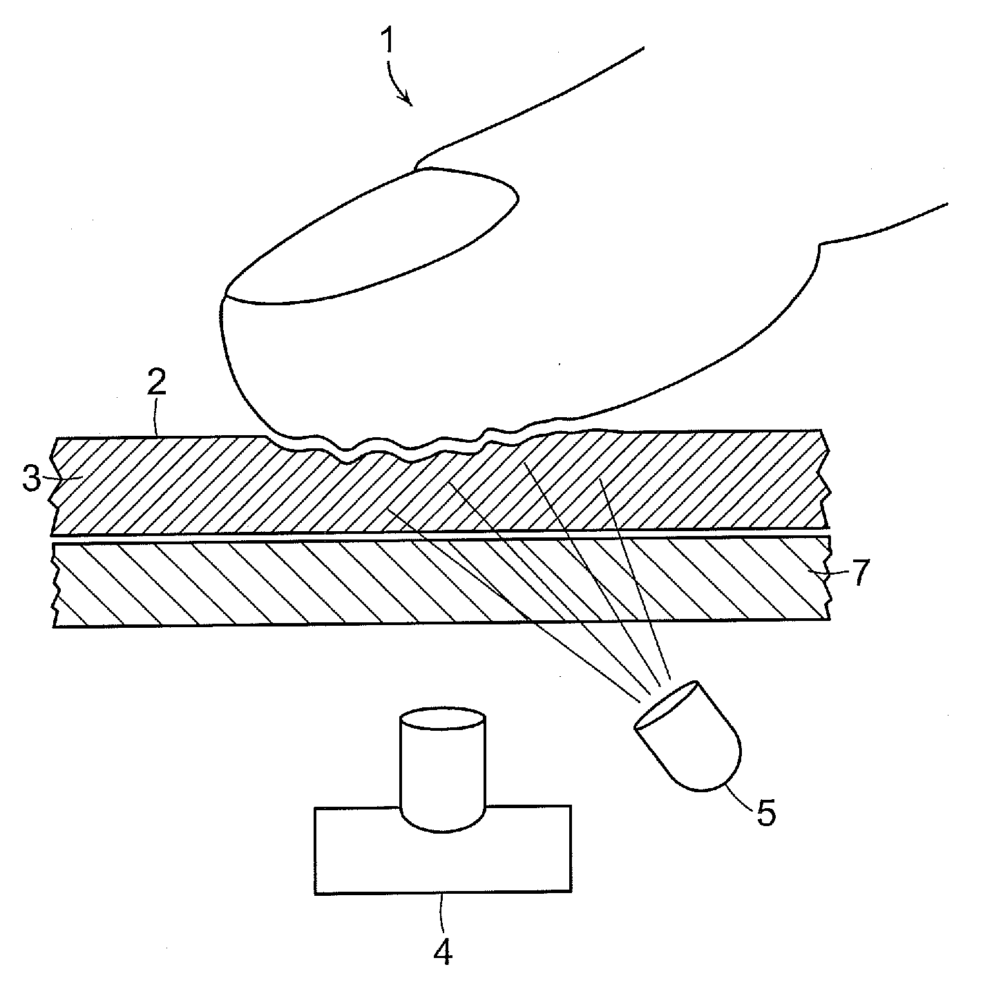
[0019]The invention provides a new approach to making tactile sensors that attain high sensitivity, high spatial resolution, and low cost. In addition, it can be built in a compliant form, so that a robot finger incorporating this sensor can deform elastically in depth, following the profile of the object being manipulated, thereby allowing good control.

[0020]An exemplary embodiment of the invention, as shown in FIG. 1, is made from slab of clear elastomer, 3, supported by a rigid sheet 7 made of glass or other rigid clear material. The surface of the elastomer is coated with a reflective layer 2, referred to as the “skin,” which is made, for example, from an elastomeric paint comprising metallic powder embedded in an elastomeric material. The skin has an inner surface (facing the elastomer) and an outer surface (facing the outside world). Light from an illuminator 5 passes through the rigid support 7 and the clear elastomer 3 and strikes the reflective skin 2. When an object such a...


PUM


Abstract

A tactile sensor includes a photosensing structure, a volume of elastomer capable of transmitting an image, and a reflective skin covering the volume of elastomer. The reflective skin is illuminated through the volume of elastomer by one or more light sources, and has particles that reflect light incident on the reflective skin from within the volume of elastomer. The reflective skin is geometrically altered in response to pressure applied by an entity touching the reflective skin, the geometrical alteration causing localized changes in the surface normal of the skin and associated localized changes in the amount of light reflected from the reflective skin in the direction of the photosensing structure. The photosensing structure receives a portion of the reflected light in the form of an image, the image indicating one or more features of the entity producing the pressure.

Description

PRIORITY INFORMATION[0001]This application claims priority from provisional application Ser. No. 61 / 073,904 filed Jun. 19, 2008, which is incorporated herein by reference in its entirety.BACKGROUND OF THE INVENTION[0002]The invention is related to the field of sensors, and in particular to tactile sensors.[0003]A variety of 2-D tactile sensors have been described in the art. In a typical sensor, an array of individual elements change some electrical property, such as resistance or capacitance, in response to pressure. The electrical changes are sensed and conveyed via wires or other electronic means to the controller or user. Another type of tactile sensor is optical. Some optical property such as luminance or reflectance changes as a result of pressure, and a light sensing system detects and conveys the signal to the controller or user.[0004]For an application such as a robot fingerpad, there are a number of properties that are desired in a tactile sensor. It should have high resol...

Claims


Application Information

Patent Timeline
Patent Type & Authority Applications(United States)
IPC IPC(8): H04N7/18G06F3/033G06F3/0354G06F3/041G06V40/12
CPCA61B5/1172A61B2562/146G01L1/24G06K9/00006G06F3/0425G06F2203/04104G06F3/03547G06V40/12G01P5/02G06V40/1335G06F18/00G06F3/042G02B2027/0187G06T19/006H04N7/142H04N7/15
Inventor ADELSON, EDWARD H.
Owner MASSACHUSETTS INST OF TECH
Why Eureka
Try Eureka