Illumination unit and liquid crystal display device

Active Publication Date: 2009-12-24
JAPAN DISPLAY CENT INC
View PDF3 Cites 65 Cited by
  • Summary
  • Abstract
  • Description
  • Claims
  • Application Information

AI Technical Summary

Problems solved by technology

The light-emitting diode has such characteristics that the light-emitting diode produces heat in operation, and that the light-emitting diode tends to easily d

Method used


Image

  • Illumination unit and liquid crystal display device
  • Illumination unit and liquid crystal display device
  • Illumination unit and liquid crystal display device

Examples


first embodiment

[0039]Next, the present invention is described.

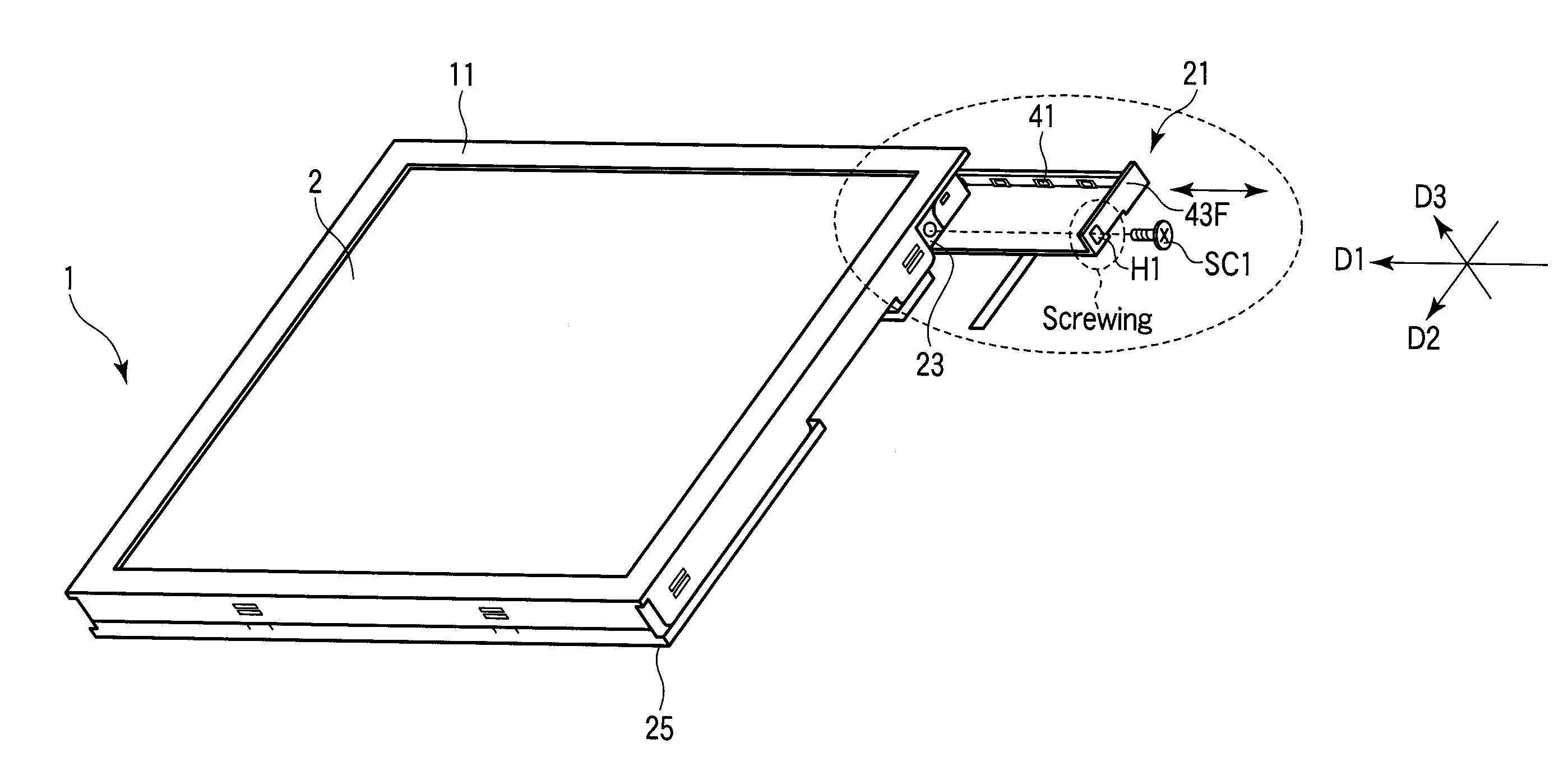
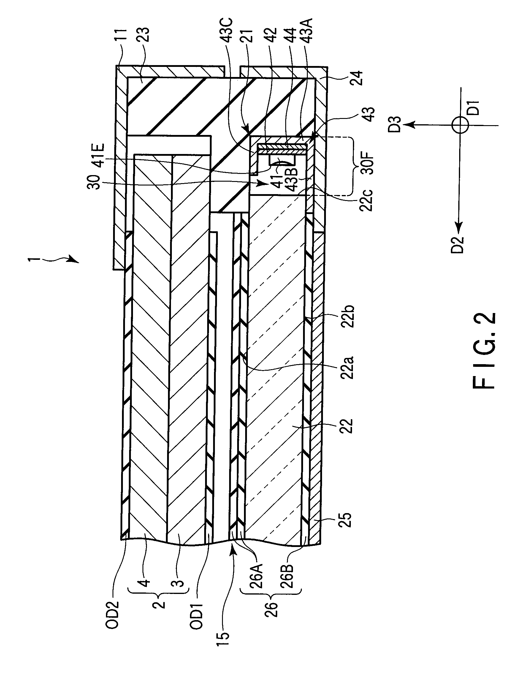
[0040]As is shown in FIG. 2, the backlight unit 15 includes a light source unit 21, a light guide 22, a frame 23, a heat radiation plate 24, a back cover 25 and an optical sheet 26.

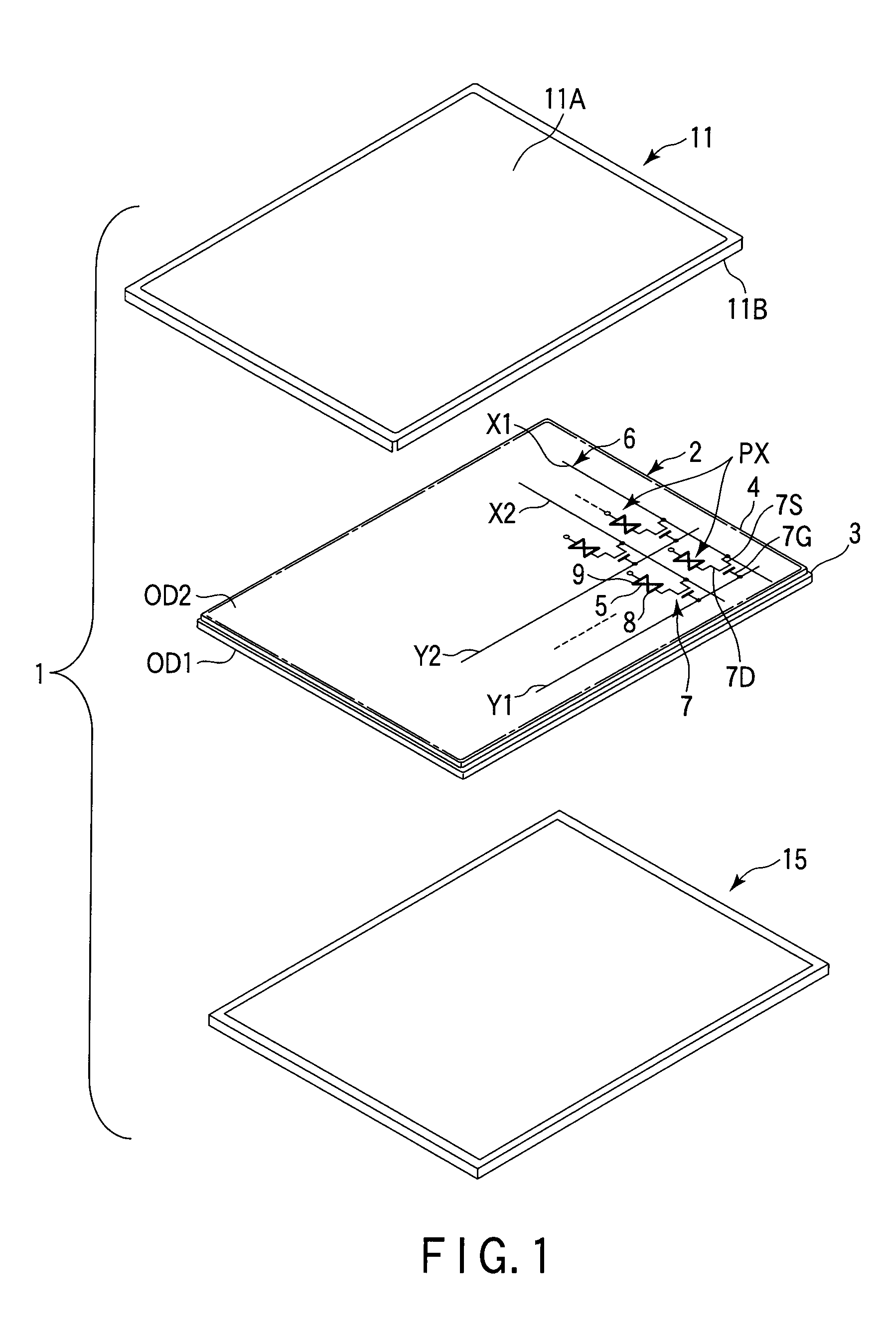
[0041]The light guide 22 has a function of guiding emission light from the light source unit 21 toward the liquid crystal display panel 2. The light guide 22 is formed of a light transmissive resin material such as an acrylic resin or a polycarbonate resin. The light guide 22 may be a wedge-shaped light guide which has a thin portion at one end and a thick portion at the other end which is opposed to the thin portion, or a planar light guide which has a substantially uniform thickness over the entirety thereof. In this embodiment, for instance, a rectangular planar light guide 22 is adopted.

[0042]The light guide 22 has a first major planar surface 22a with a rectangular shape which faces the liquid crystal display panel 2, a second major planar surface 22b wi...

second embodiment

[0077]Next, the present invention is described.

[0078]The second embodiment differs from the first embodiment in that the accommodation section 30 is configured such that the light source unit 21 is detachable from the opening portion 30F. The structural parts common to those in the first embodiment are denoted by like reference numerals, and a detailed description is omitted here.

[0079]Specifically, as shown in FIG. 9, the backlight unit 15 according to the second embodiment includes a light source unit 21, a light guide 22, a frame 23, a back cover 25 and an optical sheet 26.

[0080]The frame 23 is spaced apart from one end surface 22c of the light guide 22. An accommodation section 30 is formed between the frame 23 and the end surface 22c of the light guide 22. The accommodation section 30 is a space having a substantially U-shaped cross section between the end surface 22c of the light guide 22 and the frame 23, and the accommodation section 30 extends in the first direction D1.

[008...


PUM


Abstract

An illumination unit includes a light guide having an incidence surface, a frame which is spaced apart from the incidence surface of the light guide, an accommodation section which is formed between the incidence surface of the light guide and the frame, and a light source unit including light-emitting diodes, a film substrate on which the light-emitting diodes are amounted, a heat radiation member having a support portion which supports the film substrate and a reflection portion which extends from the support portion, and an adhesive tape which adheres the film substrate to the support portion and has heat radiation properties, the light source unit being accommodated in the accommodation section.

Description

CROSS-REFERENCE TO RELATED APPLICATIONS[0001]This application is based upon and claims the benefit of priority from prior Japanese Patent Applications No. 2008-164861, filed Jun. 24, 2008; and No. 2008-166037, filed Jun. 25, 2008, the entire contents of both of which are incorporated herein by reference.BACKGROUND OF THE INVENTION[0002]1. Field of the Invention[0003]The present invention relates to an illumination unit and a liquid crystal display device including the illumination unit.[0004]2. Description of the Related Art[0005]Liquid crystal display devices have been used in various fields as display devices of OA equipment, such as personal computers, and TV receivers, taking advantage of their features of light weight, small thickness and low power consumption. In recent years, the liquid crystal display devices have also been used as display devices of portable terminal devices such as mobile phones, car navigation devices, and game machines.[0006]As such liquid crystal displa...

Claims


Application Information

Patent Timeline
IPC IPC(8): G02F1/1333F21V7/04
CPCG02B6/0068G02B6/0085G02F2001/133628G02F1/133615G02B6/009G02F1/133628
Inventor KONO, MAKOTONAGAHAMA, HIROSHIAOSHIMA, KENJIKUBO, JIHEI
Owner JAPAN DISPLAY CENT INC
Why Eureka
Try Eureka