Method and apparatus for failure detection in lighting systems

a technology for failure detection and lighting systems, applied in the field of remote detection of light sources, can solve the problems of difficult or impossible to tell the difference through remote visual inspection between the types of bulbs, and achieve the effect of reducing electric energy use and determining the bulb type quickly and easily

Inactive Publication Date: 2009-12-24
GLOBALFOUNDRIES INC
View PDF16 Cites 23 Cited by
  • Summary
  • Abstract
  • Description
  • Claims
  • Application Information

AI Technical Summary

Benefits of technology

[0004]The desirability of and the law in the US for reducing electric energy use will require the replacement of traditional ILBs by CFLs or LEDs. It difficult or impossible to tell the difference through remote visual inspection between the types of bulbs if the bulb structure is hidden. The bulb may be contained within a frosted envelope or not viewed directly. The appearance of the light emitted is very similar for most CFLs and ILBs. The direction of the CFL industry is to produce bulbs which have a color appearance similar to that of ILBs. It is desirable to determine the bulb type quickly and easily from a distance to aid in the replacement of ILBs by CFLs in large installations. It is also desirable to determine the compliance with the law by households, businesses, and governments.

Problems solved by technology

It difficult or impossible to tell the difference through remote visual inspection between the types of bulbs if the bulb structure is hidden.

Method used


Image

  • Method and apparatus for failure detection in lighting systems
  • Method and apparatus for failure detection in lighting systems
  • Method and apparatus for failure detection in lighting systems

Examples


Embodiment Construction

[0017]The electricity supplied by power companies reverses polarity typically 110 or 120 times per second (supply of 60 Hz in US and 50 Hz in Europe), fluorescent lights turn on and off at that rate, which may cause a change in intensity or flicker. Incandescent lights do not produce this flicker because the light is produced by a hot glowing wire. This wire is not affected by electrical polarity switches, since the wire stays hot and glows steadily. Fluorescent-type lights and LEDs with high-efficiency ballasts may have a flicker rate of 20 kHz to 60 kHz.

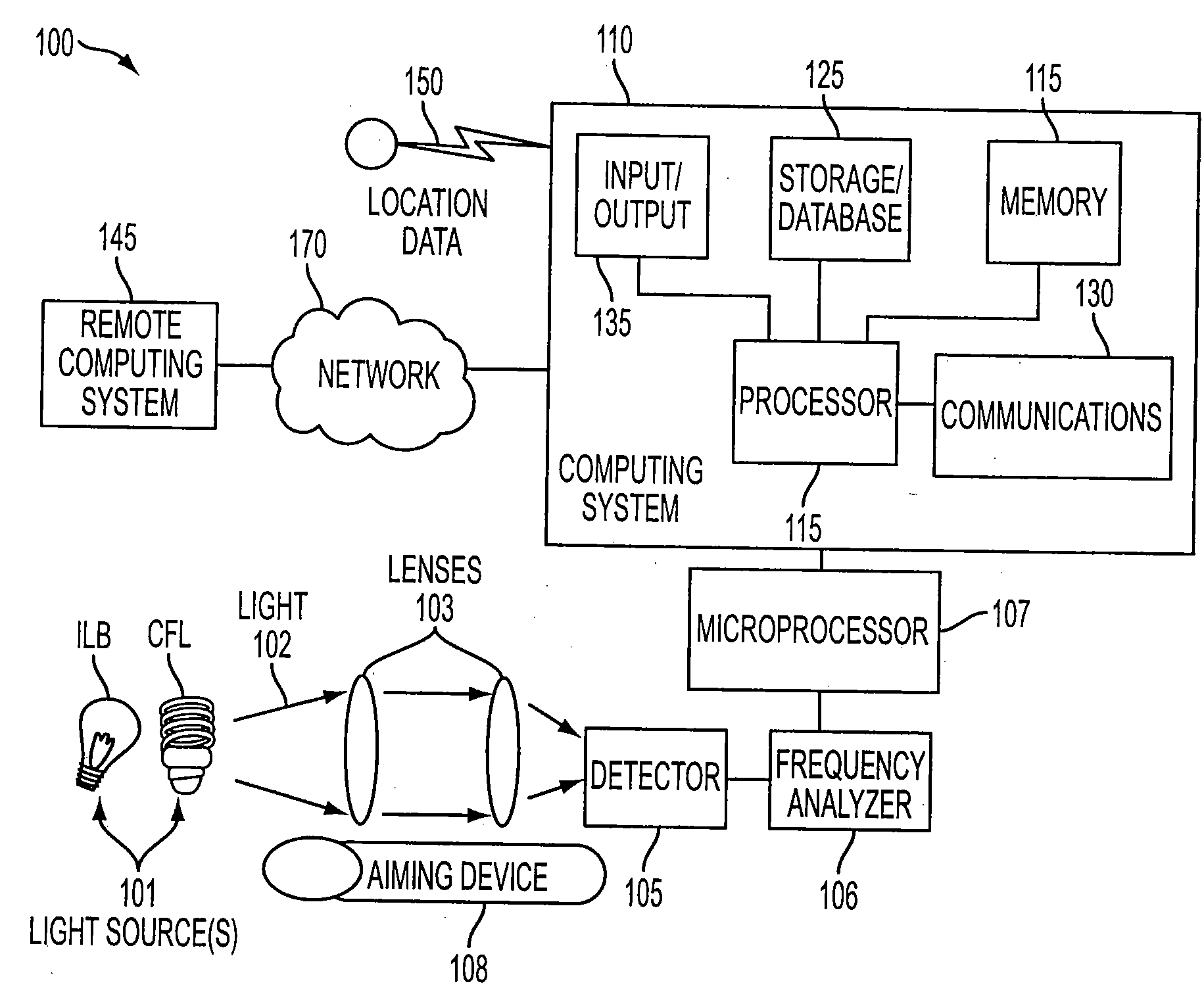
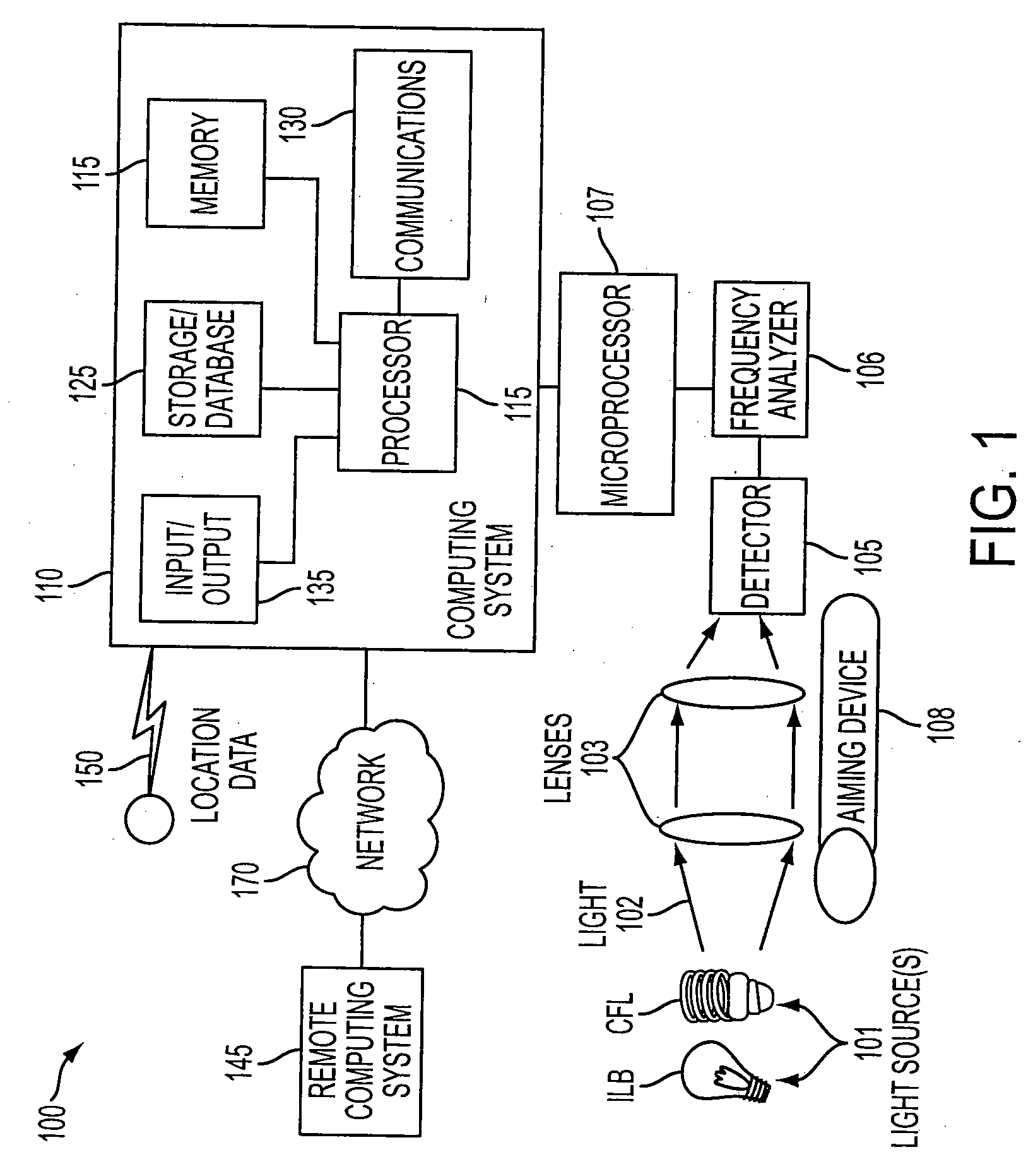
[0018]FIG. 1 is a schematic illustration of a system 100 for determining a type of light source from a plurality of light sources 101 using time domain resolution in accordance with an embodiment of the present invention. System 100 uses these innate characteristics of differing light sources 101 to remotely ascertain the type of light source.

[0019]As shown in FIG. 1, lens or lenses 103 on a detector 105 may be used to focus light ...


PUM


Abstract

A method and apparatus for continuous monitoring of a light bulb or group of light bulbs. The light emission of a light bulb is compared with known emission failure values for similar types of light bulbs, and a determination of a near failure status for the bulb is made.

Description

1. CROSS REFERENCE TO RELATED APPLICATION[0001]This application is a continuation-in-part of application entitled “Method for Determination of Efficient Lighting Use” filed on Jun. 24, 2008 and bearing application Ser. No. 12 / 145,406, the disclosure of which is incorporated herein in entirety for background information.2. FIELD OF THE INVENTION[0002]The invention relates generally to remote detection of a source of light and more specifically to the determination of bulb type and intensity of light emitted from the bulb from a distance.3. DESCRIPTION OF THE RELATED ART[0003]The IPCC, Intergovernmental Panel on Climate Change, has stated in their summary report of 2007 that most of the temperature increases seen by the world are most likely caused by anthropogenic GHG, greenhouse gas, emissions. Climate change resulting from greenhouse gas emissions has resulted in international agreements on limiting and reducing such emissions, for example, the Kyoto agreement. Even in the United S...

Claims


Application Information

Patent Timeline
Patent Type & Authority Applications(United States)
IPC IPC(8): G01J3/30G01J1/44G06F19/00G08B21/00
CPCG01J1/0488G01J1/4228G01N21/25G01J2001/4247G01J2001/4242
Inventor HAMILTON, II, RICK A.MOSKOWITZ, PAULO'CONNELL, BRIAN M.PICKOVER, CLIFFORD A.WALKER, KEITH R.
Owner GLOBALFOUNDRIES INC
Why Eureka
Try Eureka