Fixing device and image forming apparatus

a fixing device and image forming technology, applied in the direction of electrographic process apparatus, instruments, optics, etc., can solve the problems of breaking the fixing device, difficult to accurately obtain the state of temperature rise in the non-paper feed area for all sizes of paper sheets including indeterminately formed paper sheets, and high temperature of the non-paper feed area. , to achieve the effect of suppressing temperature rise, excellent thermal conductivity, and preventing any damage to the fixing devi

Active Publication Date: 2009-12-24
KONICA MINOLTA BUSINESS TECH INC
View PDF14 Cites 4 Cited by
  • Summary
  • Abstract
  • Description
  • Claims
  • Application Information

AI Technical Summary

Benefits of technology

[0008]An object of the present invention is to provide an image forming apparatus inexpensively capable of detecting rise of temperature in a fixing roller with more sufficient precision so as to effectively control temperature rise in a non-paper feed area and to prevent breakage.
[0011]In the fixing device of the invention, temperature of the soaking member is measured wherein the soaking member contacts the fixing-side rotation unit or the pressure-side rotation unit. The soaking member is excellent in thermal conductivity, so that the soaking member maintains generally flat distribution of temperature in the axial direction even when small-size recording materials are continuously fed. Therefore, measuring a temperature of part of the soaking member makes it possible to identify temperature distribution of the entire region of the fixing-side rotation unit or the pressure-side rotation unit. In short, it is possible to precisely estimate the temperature distribution of the fixing-side rotation unit or the pressure-side rotation unit including the non-paper feed area of the recording material.
[0012]The fixing operation is controlled based on the temperature of the soaking member measured by the temperature measurement section. Thus, optimal control can be performed to suppress the temperature rise in the non-paper feed area according to the estimated temperature distribution of the fixing-side rotation unit or the pressure-side rotation unit. This makes it possible to prevent any damage on the fixing device without reducing user-friendliness beyond necessity.

Problems solved by technology

This causes a problem that the temperature of the non-paper feed areas becomes higher than that of paper feed areas.
In the conventional fixing device, a highest-temperature position of the fixing roller in the axial direction thereof varies depending on the size of paper sheets to be fed Therefore, it is difficult to accurately obtain the state of temperature rise in the non-paper feed areas for all sizes of paper sheets including indeterminately formed paper sheets.
Particularly, in the case of feeding the indeterminately formed paper sheets, the state of temperature rise in the non-paper feed area of the fixing roller may be misidentified, which may cause damage such as breakage to the fixing device.

Method used


Image

  • Fixing device and image forming apparatus
  • Fixing device and image forming apparatus
  • Fixing device and image forming apparatus

Examples


first embodiment

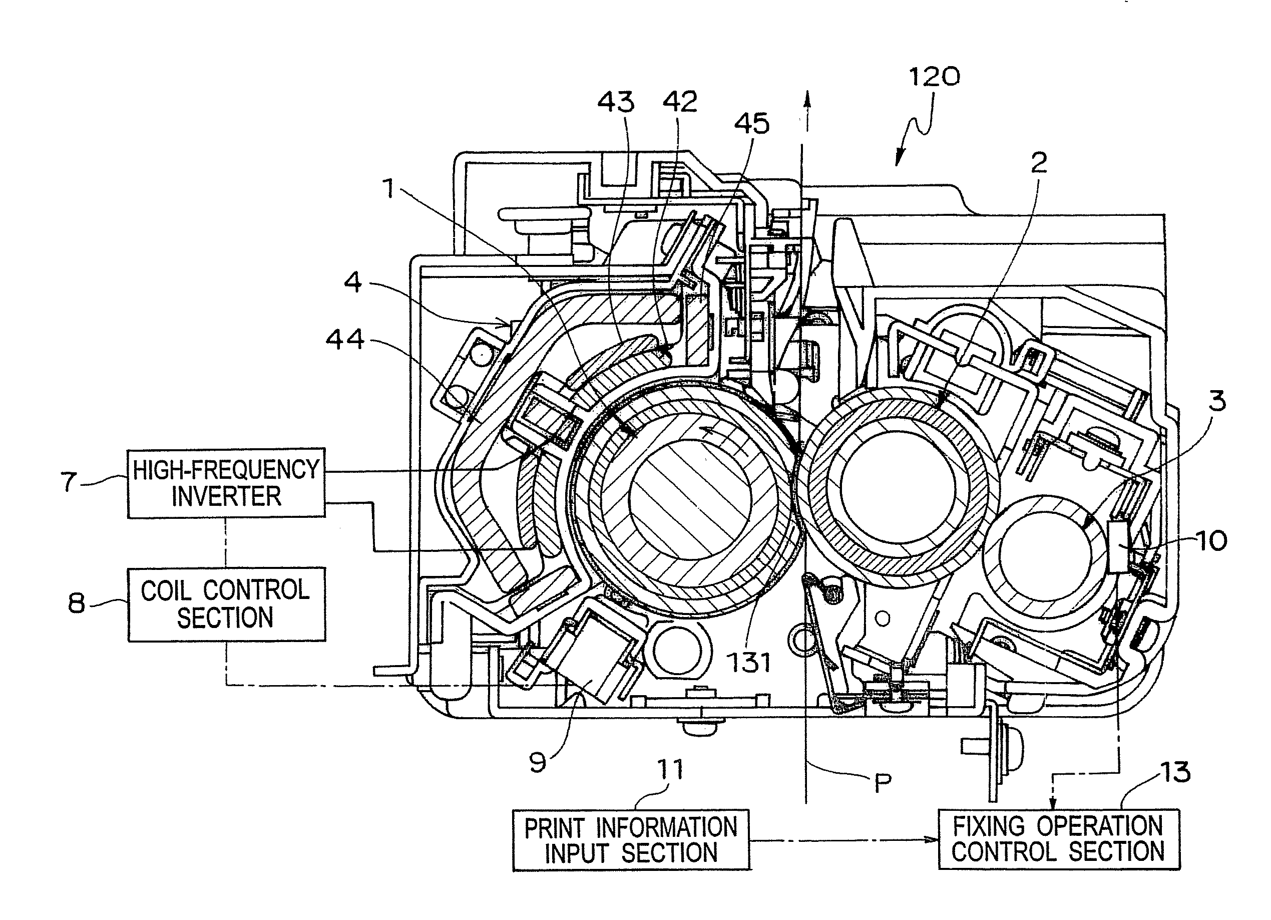
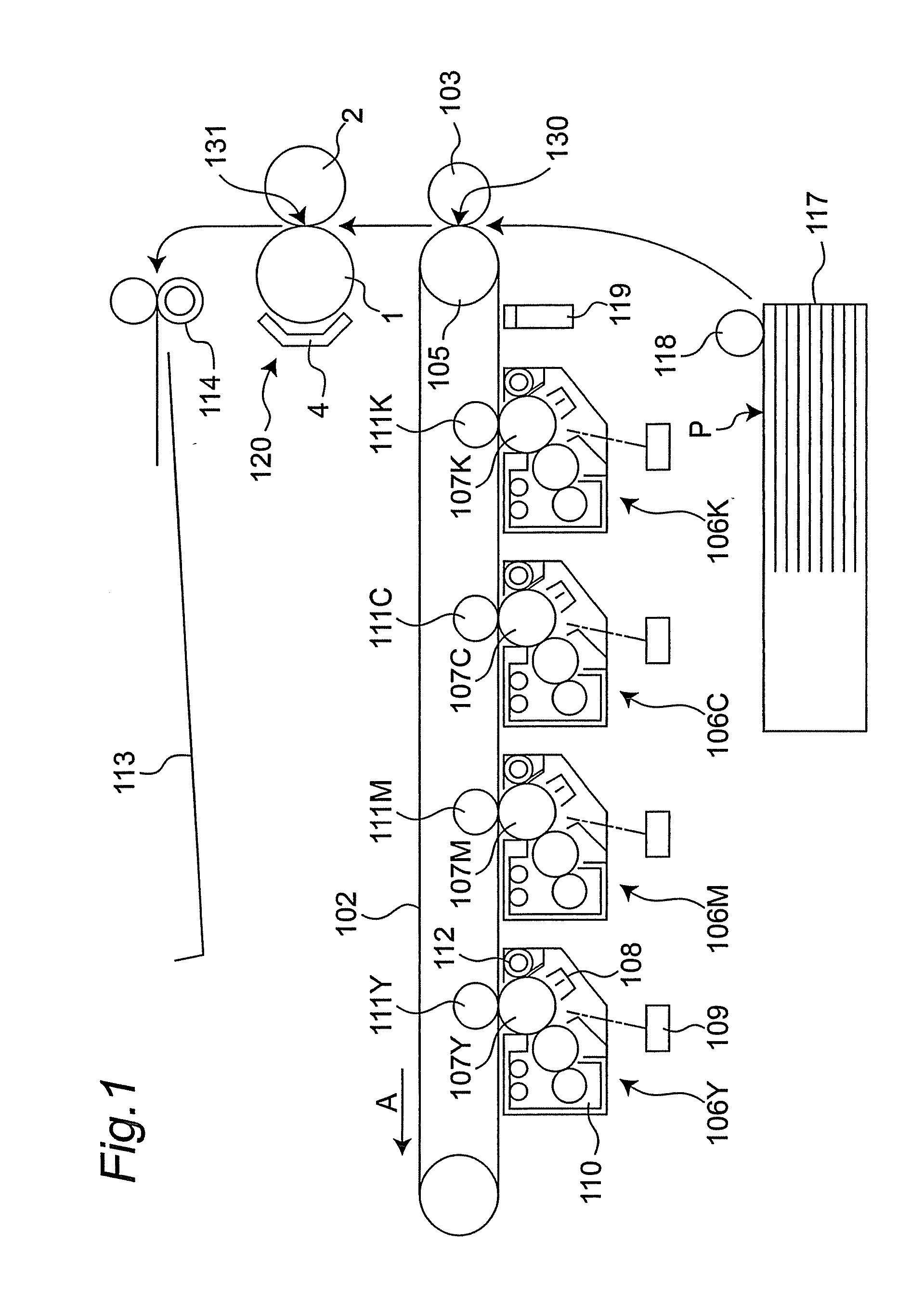
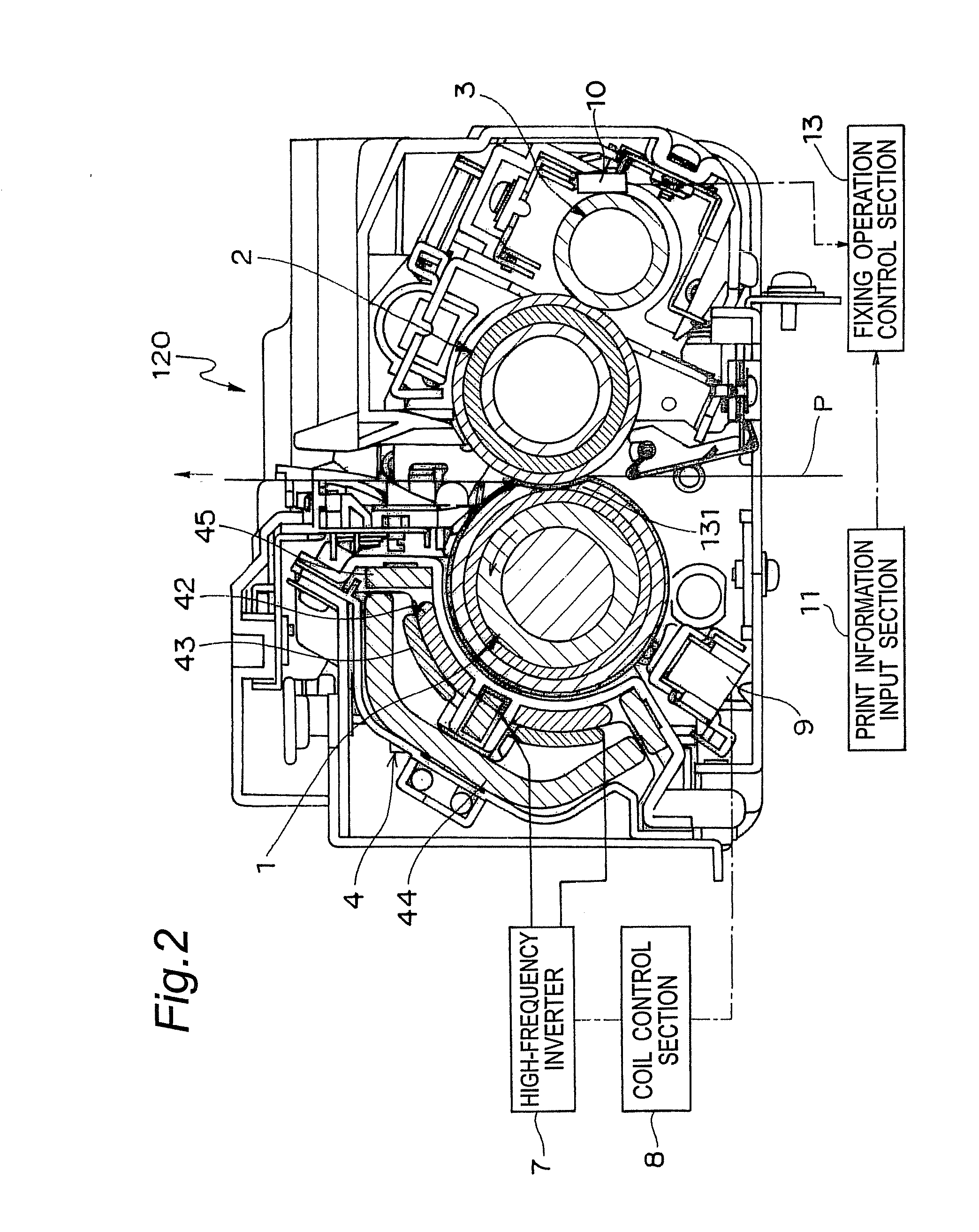
[0031]An image forming apparatus schematically shown in FIG. 1 is a color printer. The image forming apparatus has an intermediate transfer belt 102 as a belt member in a generally central inner portion of the image forming apparatus. Under a lower horizontal portion of the intermediate transfer belt 102, four imaging units 106Y, 106M, 106C and 106K are juxtaposed along with the intermediate transfer belt 102, wherein the four imaging units 106Y, 106M, 106C and 106K respectively correspond to colors of yellow (Y), magenta (M), cyan (C) and black (K). The imaging units 106Y, 106M, 106C and 106K have photoconductor drums 107Y, 107M, 107C and 107K, respectively.

[0032]A charger 108, a print head section 109, a developing device 110, a primary transfer roller 111Y, 111M, 111C or 111K, and a cleaner 112 are placed in this order around the photoconductor drum 107Y, 107M, 107C or 107K along the rotation direction thereof. The primary transfer rollers 111Y, 111M, 111C and 111K respectively f...

second embodiment

[0099]FIG. 10 shows a fixing device in a second embodiment of the present invention. The second embodiment is different from the first embodiment in structure of the heating section. Other structures than the heating section are identical to those in the first embodiment, and therefore, the description thereof is omitted.

[0100]As shown in FIG. 10, a heater 20 is used as a heating section. The heater 20 is placed inside the fixing roller 1 for heating the fixing roller 1.

[0101]The heater 20 has a central heater 20a for heating an axially central portion of the fixing roller 1 and end heaters 20b, 20c for heating both the axial end portions of the fixing roller 1.

[0102]The central heater 20a heats the paper feed area of the small-size paper sheet P in the contact part between the fixing roller 1 and the pressure roller 2. The end heaters 20b, 20c heat the non-paper feed area of the small-size paper sheet P in the contact part between the fixing roller 1 and the pressure roller 2.

[0103...


PUM


Abstract

A fixing device includes a fixing roller, a pressure roller and a soaking roller. Temperature of the soaking roller, which contacts with the pressure roller, is measured by a temperature measurement section. This makes it possible to precisely estimate the temperature distribution of the fixing roller and the pressure roller including a non-paper feed area of paper sheets. Based on the temperature of the soaking roller, fixing operation is controlled by a fixing operation control section. Thereby, optimal control can be implemented to suppress the temperature rise in the non-paper feed area according to the estimated temperature distribution of the fixing roller and the pressure roller.

Description

CROSS-REFERENCE TO RELATED APPLICATION[0001]This application is based on application No. 2008-161532 filed in Japan, the entire content of which is hereby incorporated by reference.TECHNICAL FIELD[0002]The present invention relates to a fixing device for use in image forming apparatuses such as copying machines, printers and facsimiles, and to an image forming apparatus using the fixing device.BACKGROUND ART[0003]Conventionally, there have been a fixing device including a fixing roller and a pressure roller (see JP 10-74017 A). The fixing roller is heated by induction heating. The fixing roller and the pressure roller respectively heats and pressurizes recording paper so as to fix images on the recording paper.[0004]When small-size recording paper is continuously fed, heat is not removed in non-paper feed areas of the fixing roller and the pressure roller. This causes a problem that the temperature of the non-paper feed areas becomes higher than that of paper feed areas.[0005]As a s...

Claims


Application Information

Patent Timeline
Patent Type & Authority Applications(United States)
IPC IPC(8): G03G15/20
CPCG03G15/2042
Inventor SHIMIZU, YOSUKE
Owner KONICA MINOLTA BUSINESS TECH INC
Why Eureka
Try Eureka