

Liquid application method, liquid application apparatus and image forming apparatus
- Summary
- Abstract
- Description
- Claims
- Application Information
AI Technical Summary
Benefits of technology
Problems solved by technology
Method used
Image

Examples
first embodiment
General Composition of Inkjet Recording Apparatus
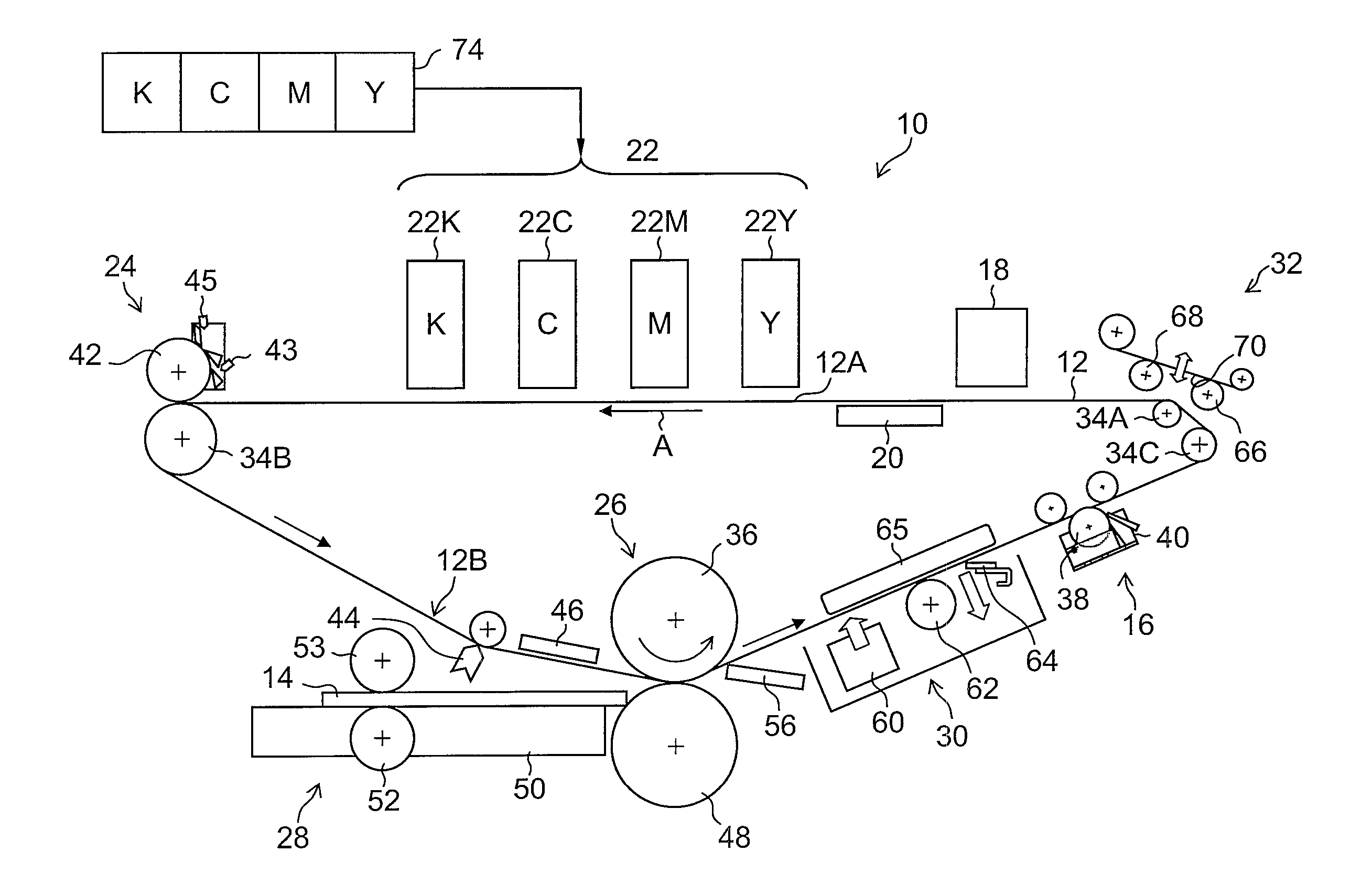
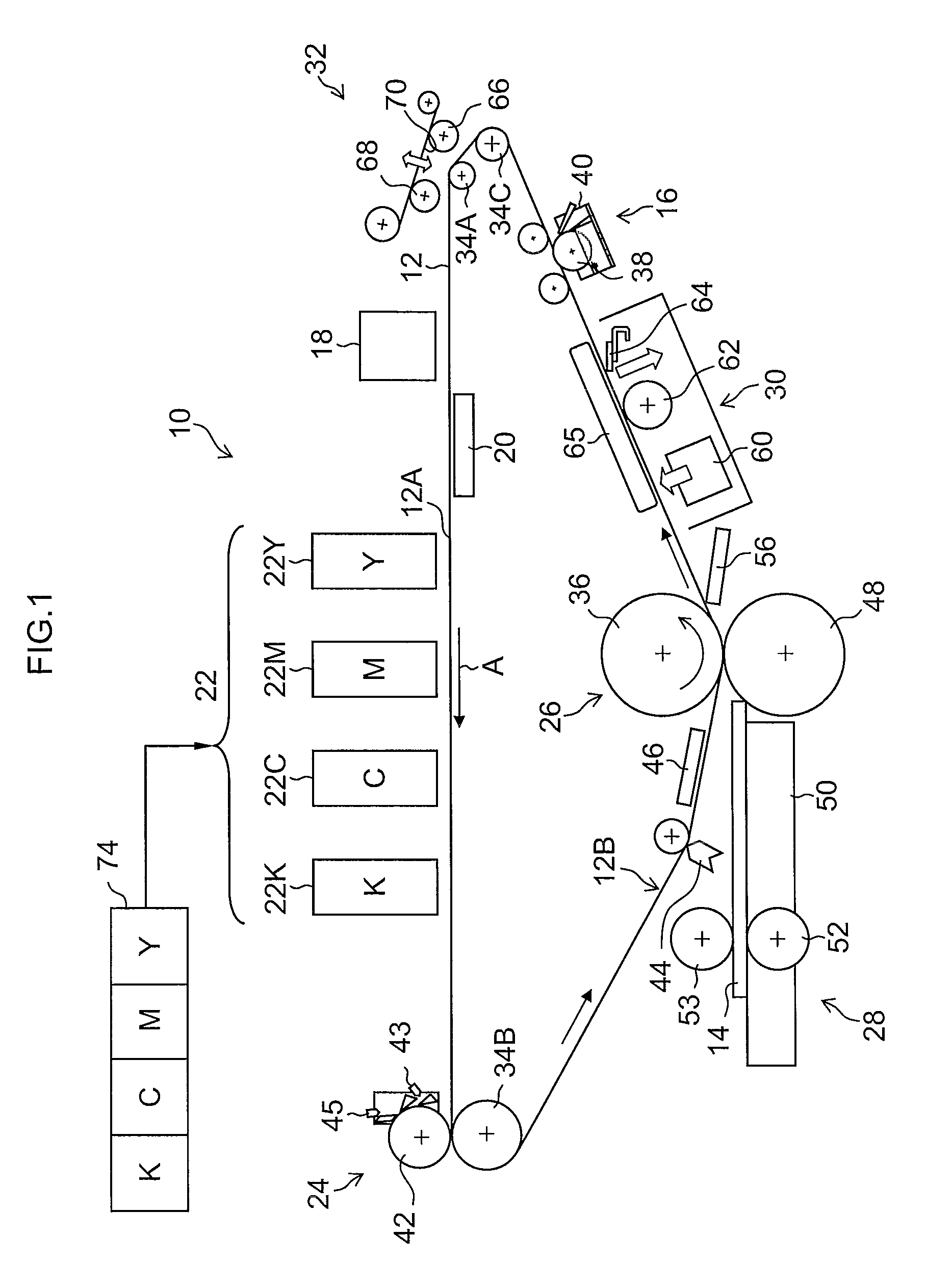
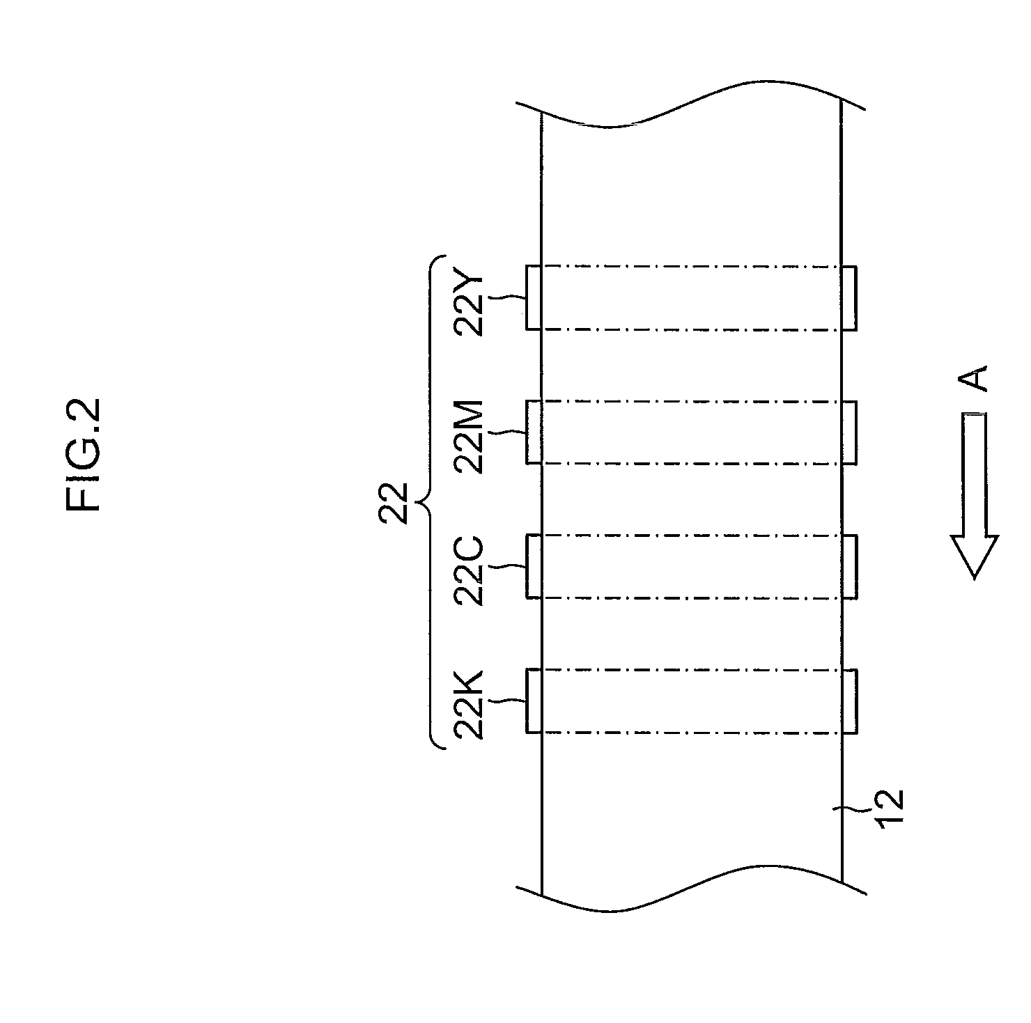
[0091]Firstly, an inkjet recording apparatus which forms an image forming apparatus according to an embodiment of the present invention will be described. FIG. 1 is a diagram of the general composition of an inkjet recording apparatus according to a first embodiment. As illustrated in FIG. 1, the inkjet recording apparatus 10 according to the present embodiment is a recording apparatus using a transfer method which records an image (primary image) on an intermediate transfer body 12, which is a non-permeable body, and then forms a main image (secondary image) by transferring this image to a recording medium 14, such as a normal paper. The principle compositional elements of this inkjet recording apparatus 10 are: a treatment liquid application unit 16 (corresponding to the “liquid application apparatus” according to the present invention) which applies an aggregation treatment agent (hereinafter, also referred to simply as “treatment ...
example 1
Treatment Liquid Example 1
[0157]A treatment liquid (Example 1) is prepared according to the composition illustrated in Table 1. Thereupon, the physical properties of the treatment liquid (Example 1) thus obtained were measured, and the pH was 3.6, the surface tension was 28.0 mN / m, and the viscosity was 3.1 mPa·s.
TABLE 1MaterialWeight %2-pyrrolidone-5-carboxylic acid10(made by Tokyo Chemical Industry Co., Ltd.)Lithium hydroxide-hydride (made by Wako Pure2Chemical Industries, Ltd.)Olfine E1010 (made by Nissin Chemical Industry Co., Ltd.)1Deionized water87
example 2
Treatment Liquid Example 2
[0158]Moreover, a treatment liquid (Example 2) containing a surfactant is prepared according to the composition illustrated in Table 2. Thereupon, the physical properties of the treatment liquid (Example 2) thus obtained were measured, and the pH was 3.5, the surface tension was 18.0 mN / m, and the viscosity was 10.1 mPa·s.
TABLE 2MaterialWeight %2-pyrrolidone-5-carboxylic acid10(made by Tokyo Chemical Industry Co., Ltd.)Lithium hydroxide-hydride (made by Wako Pure2Chemical Industries, Ltd.)Olfine E1010 (made by Nissin Chemical Industry Co., Ltd.)1Fluorine surfactant 13Deionized water84
[0159]The chemical formula of the fluorine surfactant 1 used in Table 2 is as follows.
[0160]Moreover, when the viscosity of the treatment liquid (Example 2) was investigated after leaving the treatment liquid for three days, the viscosity rose from 10.1 mPa·s to 39.2 mPa·s, and the liquid could be applied without the occurrence of a beading effect, even onto a silicone rubber, ...
PUM
| Property | Measurement | Unit |
|---|---|---|
| Angle | aaaaa | aaaaa |
| Angle | aaaaa | aaaaa |
| Surface energy | aaaaa | aaaaa |
Abstract
Description
Claims
Application Information