Electrical connector with slotted shield

a technology of electrical connectors and shields, applied in the direction of coupling device details, coupling device connections, coupling protective earth/shielding arrangements, etc., can solve problems such as other damage to electronic equipmen

Active Publication Date: 2009-12-24
TYCO ELECTRONICS LOGISTICS AG (CH)
View PDF7 Cites 13 Cited by
  • Summary
  • Abstract
  • Description
  • Claims
  • Application Information

AI Technical Summary

Benefits of technology

[0005]in One embodiment, an electrical connector housing includes a housing and a shield. The housing has an interior chamber that includes an inner surface extending between a housing mating end and a housing back end. The housing mating end is configured to mate with a mating electrical connector. The inner surface has loading and transition portions, with the loading portion located proximate to the housing mating end and the transition portion located proximate to the housing back end. The shield is shaped to fit in the interior chamber and extends between

Problems solved by technology

The rim, however, also can present problems in the manufacture and tooling processes involved in manufact

Method used


Image

  • Electrical connector with slotted shield
  • Electrical connector with slotted shield
  • Electrical connector with slotted shield

Examples


Embodiment Construction

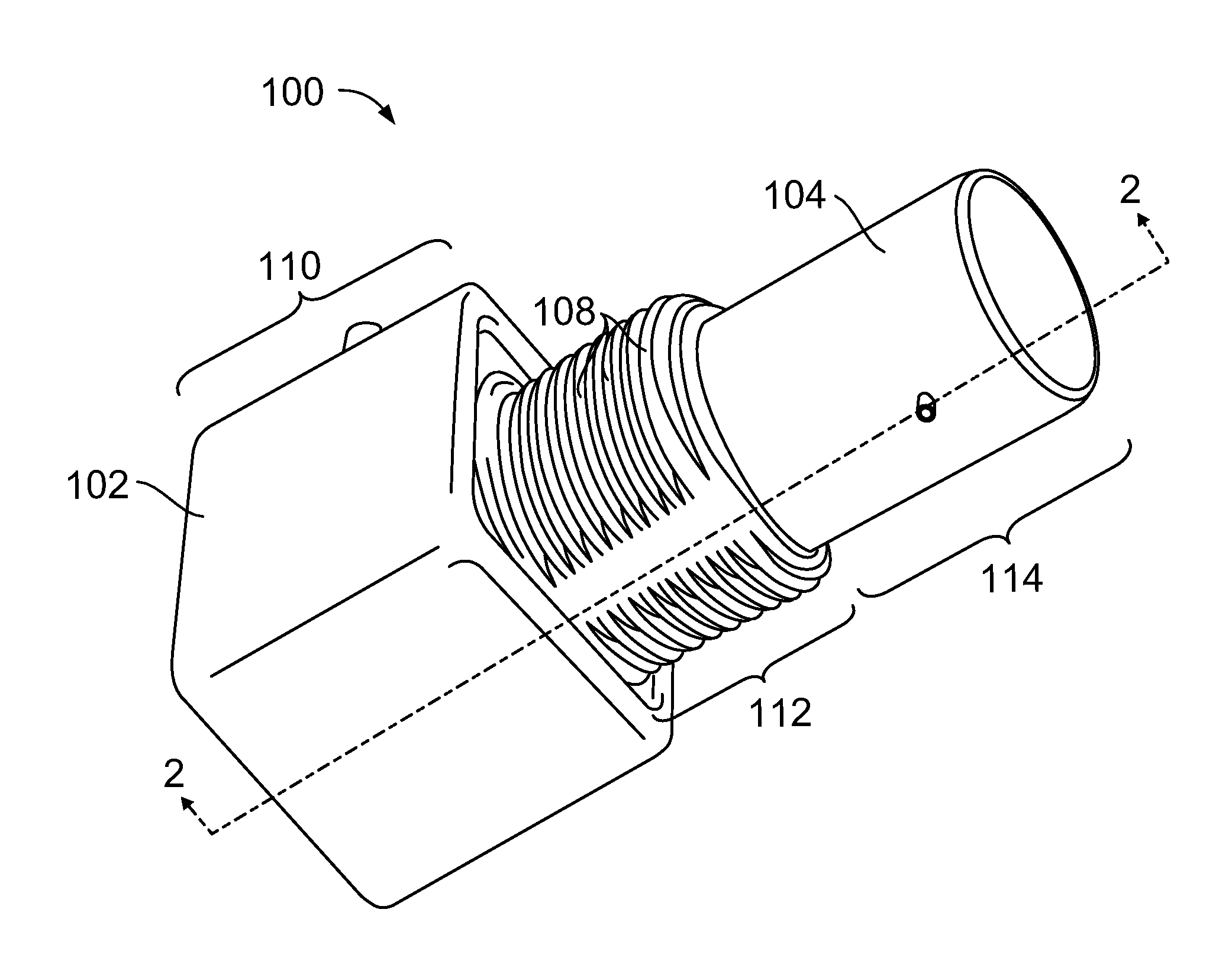
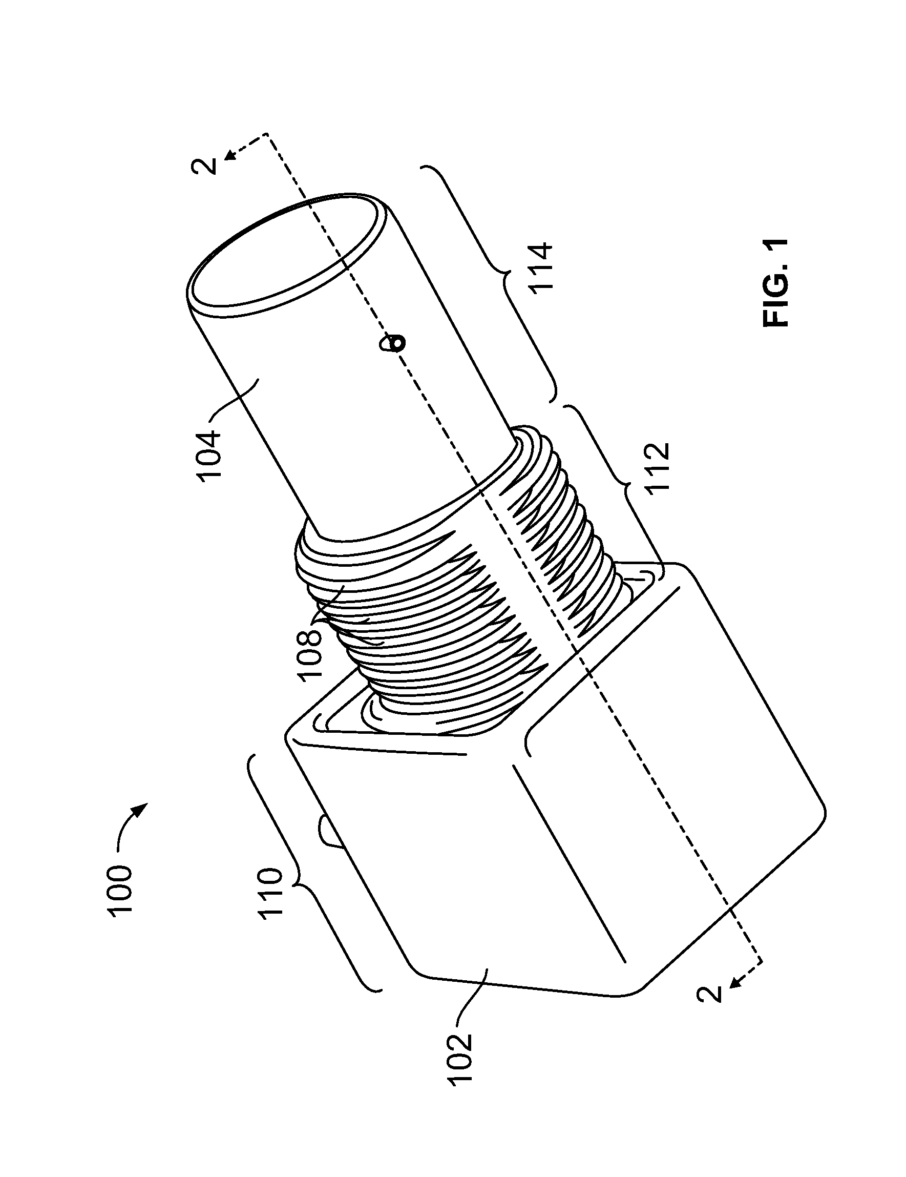
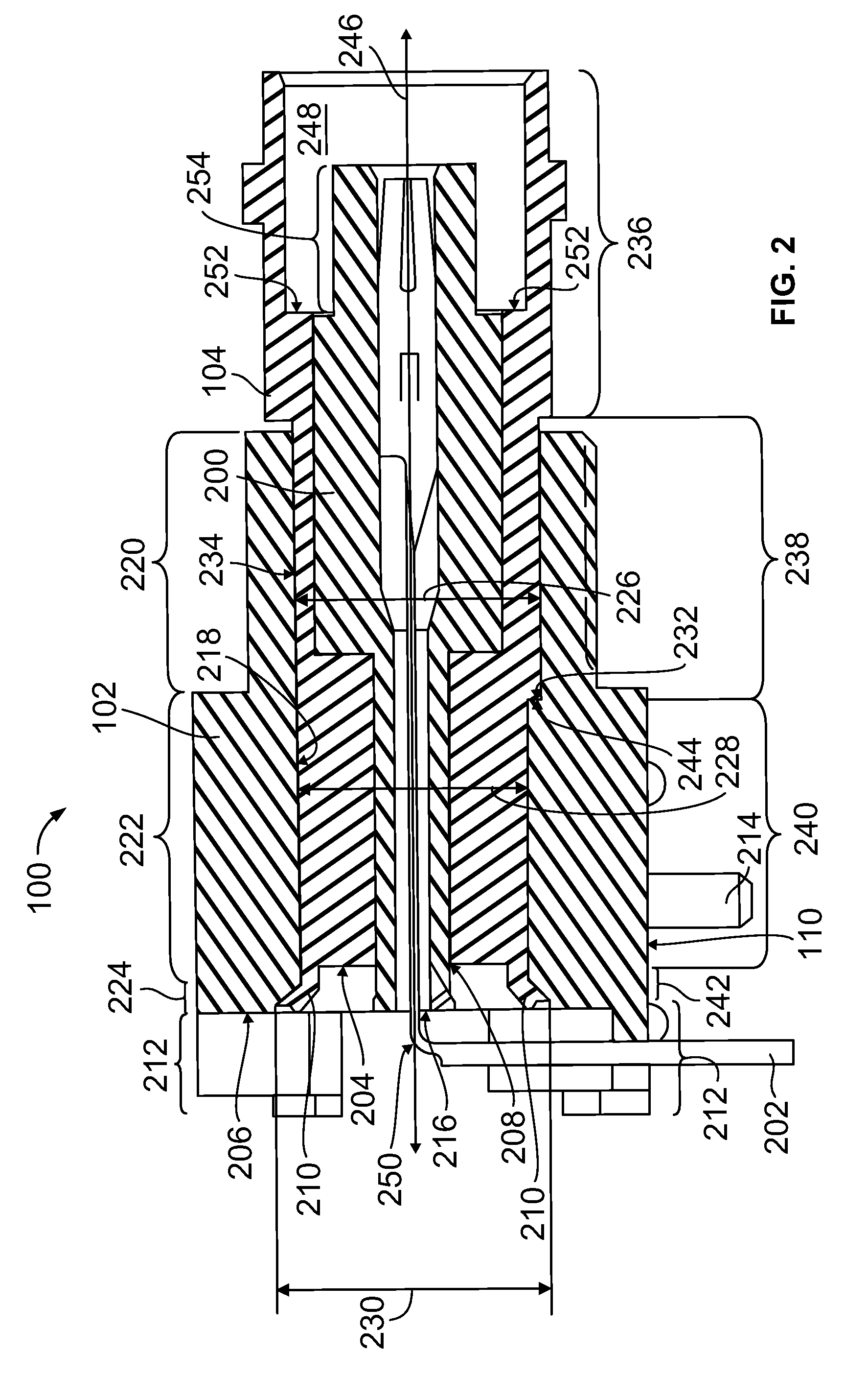
[0012]FIG. 1 is a perspective view of an electrical connector assembly 100 according to one embodiment. The connector assembly 100 includes a housing 102 and a shield 104, with the shield 104 being partially held within the housing 102. A dielectric 200 (shown in FIG. 2) and a signal contact 202 (shown in FIG. 2) are held within the shield 104. In one embodiment, the connector assembly 100 is an RF connector. For example, the signal contact 202 may be an electrical contact capable of carrying a data or power signal.

[0013]The shield 104 may shield the connector assembly 100 from electromagnetic interference. The shield 104 comprises, is formed of, or has an outside surface that is coated with a conductive material. For example, the shield 104 may be formed of zinc, copper or an alloy containing copper. Other conductive metals, however, can be used in alternative embodiments. For example, the shield 104 may be formed of a die cast metal. In one embodiment the shield 104 has a conducti...


PUM


Abstract

A connector housing includes a housing and a shield. The housing has an interior chamber extending between housing mating and back ends. The inner surface has loading and transition portions, with the loading portion located proximate to the housing mating end and the transition portion located proximate to the housing back end. The shield is shaped to fit in the interior chamber and extends between a shield mating end and a shield back end. The shield back end includes a ground contact opening. The shield includes a rim protruding from the shield back end that extends around a portion of an outer periphery of the shield back end. The rim includes a plurality of rim ends separated by a gap. The rim engages the transition portion to prevent the shield being removed through the housing mating end and the gap exposes a portion of the transition portion.

Description

BACKGROUND OF THE INVENTION[0001]The subject matter herein relates generally to electrical connectors, and more particularly, to electrical connectors having an electromagnetic (“EM”) shield.[0002]Some known electrical connectors, include a shield disposed within a housing. A portion of the shield may protrude from one cud of the housing. For example, a rim extending entirely around a periphery of one end of the shield may partially protrude from the housing. A pair of openings in the shield that are surrounded by the rim may be provided for a signal contact and a ground contact. For example, the signal contact (nay be inserted through, one of the openings and may pass through the shield and the housing to a mating end of the connector. A second opening may receive a ground contact that is electrically connected to an electrical ground. The ground contact may then connect the shield to the electrical ground.[0003]The shield may be secured in the housing by bending, or flaring, the r...

Claims


Application Information

Patent Timeline
IPC IPC(8): H01R13/648
CPCH01R43/20H01R24/50H01R43/002H01R2103/00
Inventor BLOCK, MICHAEL J.WEIDNER, KEVIN E.
Owner TYCO ELECTRONICS LOGISTICS AG (CH)
Why Eureka
Try Eureka