
Neoplastic cell destruction device and method utilizing low frequency sound waves to disrupt or displace cellular materials

Inactive Publication Date: 2009-12-24
KENNY DANIELE
View PDF29 Cites 2 Cited by
  • Summary
  • Abstract
  • Description
  • Claims
  • Application Information

AI Technical Summary

Benefits of technology

[0022]Thus, an object of the embodiments of the present invention is to provide a neoplasm cell destruction device utilizing low frequency sound waves to disrupt or displace cellular materials, which avoids the disadvantages of the prior art.

Problems solved by technology

If the neoplasm cells per se became damaged, they could therefore not heal themselves and they would therefore eventually be destroyed.

Method used


Image

  • Neoplastic cell destruction device and method utilizing low frequency sound waves to disrupt or displace cellular materials
  • Neoplastic cell destruction device and method utilizing low frequency sound waves to disrupt or displace cellular materials
  • Neoplastic cell destruction device and method utilizing low frequency sound waves to disrupt or displace cellular materials

Examples


first embodiment

D. The Configuration of the Target Interface 140

[0070]The configuration of a first embodiment of the target interface 140 can best be seen in FIG. 3, which is a diagrammatic perspective view of a first embodiment of the target interface utilized to treat the entire body of a patient, and as such will be discussed with reference thereto.

[0071]The target interface 140 includes a tub 150. The tub 150 of the target interface 140 defines an internal chamber 152 in which a body 154 of a patient 156 is placeable when the neoplastic target 44 is wide spread throughout the body 154 of the patient 156.

[0072]The first transducer 28, the second transducer 32, and the nth transducer 36 are disposed on the tub 150 of the target interface 140, with the first waveform 30, the second waveform 34, and the nth waveform 38 emanating therefrom into the internal chamber 152 in the tub 150 of the target interface 140.

[0073]The target interface 140 further includes a liquid 158. The liquid 158 of the targe...

second embodiment

E. The Configuration of the Target Interface 240.

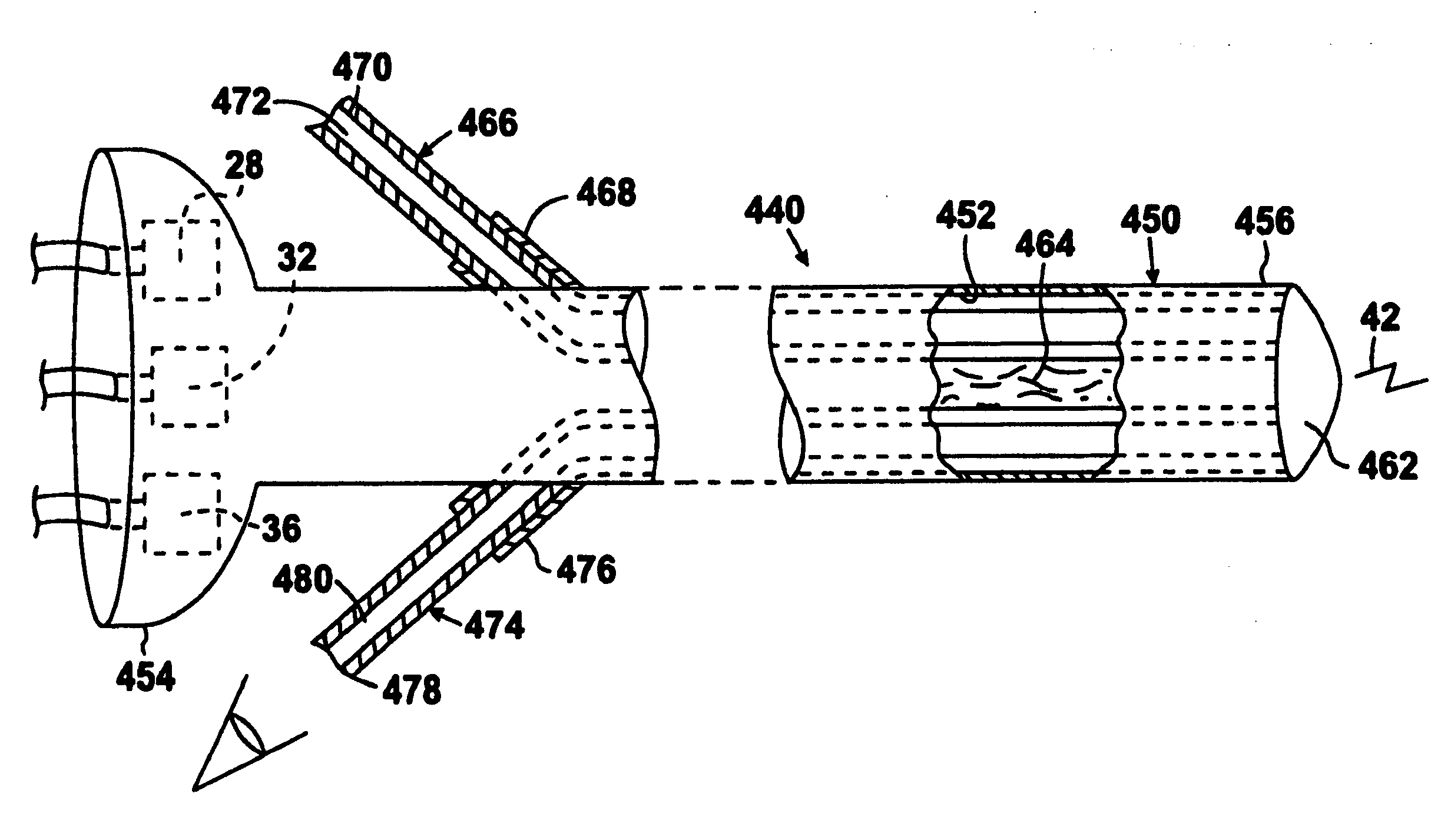
[0074]The configuration of a second embodiment of the target interface 240 can best be seen in FIG. 4, which is a diagrammatic perspective view of a second embodiment of the target interface utilized to treat a small area of a patient, and as such, will be discussed with reference thereto.

[0075]The target interface 240 includes a hollow, elongated, slender, hand-held, and tubular body 250. The hollow, elongated, slender, hand-held, and tubular body 250 of the target interface 240 contains an internal chamber 252, has a proximal end 254 and a distal treatment end 256, and is holdable in, and orientatably controllable by, a hand 258 of a user 260.

[0076]The hollow, elongated, slender, hand-held, and tubular body 250 of the target interface 240 can preferably be plastic and / or metal, but is not limited to that.

[0077]The first transducer 28, the second transducer 32, and the nth transducer 36 are disposed at the proximal end 254 of the hol...

third embodiment

F. The Configuration of the Target Interface 340

[0081]The configuration of a third embodiment of the target interface 340 can best be seen in FIG. 5, which is a diagrammatic perspective view of a third embodiment of the target interface utilized to treat a large area of a patient, and as such will be discussed with reference thereto.

[0082]The target interface 340 includes a hollow and hand-held body 350. The hollow and hand-held body 350 of the target interface 340 contains an internal chamber 352, has an upper wall 354 and a lower treatment wall 356, is holdable in a hand 358 of a user 360, and is contactable at least in close proximity to the neoplastic target 44 when the neoplastic target 44 is contained in a large area in a body of a patient.

[0083]The hand 358 of a user 360 is passable through a loop 361 of the target interface 340 that is accessible from the upper wall 354 of the hollow and hand-held body 350 of the target interface 340, but is not limited to that.

[0084]The hol...


PUM


Abstract

A neoplasm cell destruction device utilizing low frequency sound waves to disrupt or displace cellular materials in neoplastic cells so as to damage and ultimately destruct the neoplastic cells. The device includes a plurality of signal generators, a controller, a plurality of amplifiers, a plurality of transducers, and a target interface. The controller is in electrical communication with, and generates timing and control signals for simultaneously activating, the plurality of signal generators. Each amplifier is in electrical communication with a respective signal generator and amplifies the signal generated by the respective signal generator so as to form an amplified signal. Each transducer is in electrical communication with a respective amplifier and is driven by the amplified signal formed by the respective amplifier. The target interface combines the waveforms formed by the plurality of transducers to form an interference wave that is a low frequency sound wave.

Description

1. CROSS REFERENCE TO RELATED APPLICATIONS[0001]The instant patent application is a Continuation-In-Part patent application of patent application Ser. No. 11 / 134,011, filed May 20, 2005, entitled NEOPLASM CELL DESTRUCTION DEVICE, incorporated herein by reference thereto, and which is a Continuation patent application of patent application Ser. No. 08 / 777,452, filed Dec. 30, 1996, entitled NEOPLASTIC CELL DESTRUCTION DEVICE AND METHOD UTILIZING LOW FREQUENCY SOUND WAVES TO DISRUPT OR DISPLACE CELLULAR MATERIALS, now U.S. Pat. No. 7,416,535 B1, issued on Aug. 26, 2008, and incorporated herein by reference thereto.2. BACKGROUND OF THE INVENTION[0002]A. Field of the Invention[0003]The embodiments of the present invention relate to a biological cell destruction device, and more particularly, the embodiments of the present invention relate to a neoplasm cell destruction device utilizing low frequency sound waves to disrupt or displace cellular materials in neoplastic cells.[0004]B. Descri...

Claims


Application Information

Patent Timeline
IPC IPC(8): G01S15/00A61B8/00
CPCA61H23/0236A61B8/4209A61B8/4227
Inventor KENNY, DANIELE
Owner KENNY DANIELE
Learn More