Signal-processing method for use in a force-measuring device and force-measuring device

Active Publication Date: 2009-12-24
METTLER TOLEDO GMBH
View PDF3 Cites 0 Cited by
  • Summary
  • Abstract
  • Description
  • Claims
  • Application Information

AI Technical Summary

Benefits of technology

[0029]This characteristic leads to a so-called hysteresis effect in that each output value inherently contains a certain amount of past history and, accordingly, the output value always depends on the direction in which the output value was arrived at. With this hysteresis effect, short-term fluctuations can be further reduced and, accordingly, a very solid display can be achieved.
[0030]With a suitable choice of the correction parameter and thus of the step size of the changes of the integral value the robustness, i.e. the ability to resist fluctuations, of the display can be improved significantly, for example by a factor of three, without causing a delay in the response.
[0031]A preferred embodiment further includes a program which can be executed in a signal-processing unit, in particular a display-processing unit or an arithmetic unit, and which serves to calculate an output value according to the method. This allows a very high degree of flexibility and the inc

Problems solved by technology

Particularly in applications where the measurement accuracy is high, it is known that even the smallest disturbances of the measurement signal can lead to considerable instabilities of the output values.
As a result of the display fluctuations, it becomes difficult or even impossible to read these values, in particular their lowest decimal places or finest scale graduations.
As a further consequence, these instabilities can cause problems such as inaccuracies downstrea

Method used


Image

  • Signal-processing method for use in a force-measuring device and force-measuring device
  • Signal-processing method for use in a force-measuring device and force-measuring device
  • Signal-processing method for use in a force-measuring device and force-measuring device

Examples


Embodiment Construction

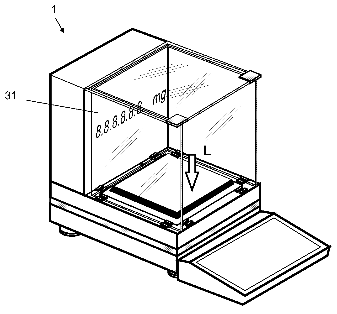
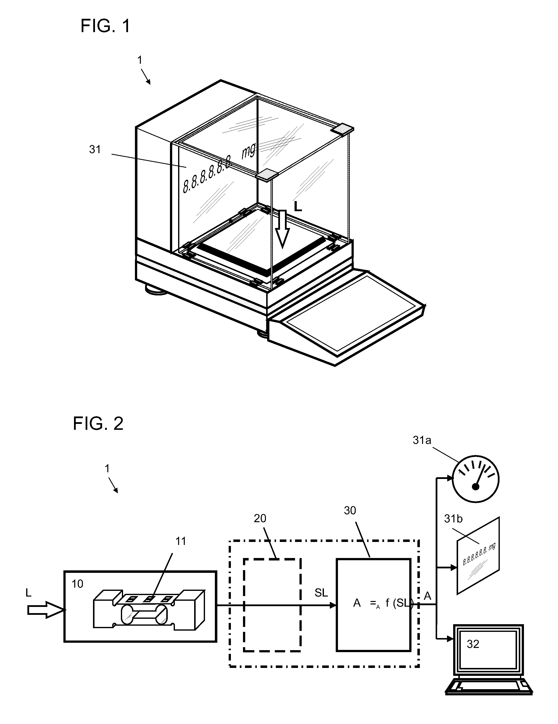
[0043]FIG. 1 is a perspective view of a balance 1 with an indicator unit 31 in an exemplary embodiment wherein the action of a load L is symbolically indicated. The balance 1 is equipped with a display-processing unit (not shown in FIG. 1) which has the task to attain an accurate and stable output value A of the indicator unit 31, wherein the latter can for example consist of a digital liquid crystal display.

[0044]FIG. 2 shows the block diagram of the balance 1 of FIG. 1 in an exemplary illustration. The measurement transducer 10, whose operating principle is in this example based on the deformation of strain gauges 11, generates a measurement signal which corresponds to the force L acting on the measurement transducer. The measurement transducer 10 is connected to a display-processing unit 30, either directly or through a pre-processing unit 20 (as shown in FIG. 2) in order to transmit the measurement signal SL to the display-processing unit 30. As indicated in FIG. 2, the display-...


PUM


Abstract

A method, an arrangement and a program process a measurement signal generated in a measurement transducer of an electronic force-measuring device, particularly a balance. The generated measurement signal corresponds to the force acting on the transducer. The measurement signal is entered directly or by way of a pre-processing stage into a display function which assigns corresponding output values to the values of the measurement signal. The output values are subsequently presented in a display or passed on for further processing. The input range of the display function contains a capture range, so that the values of the measurement signal that lie within the capture range are assigned a common output value by the display function, and the position of the capture range within the input range is controlled dependent on the generated measurement signal.

Description

CROSS-REFERENCE TO RELATED APPLICATIONS[0001]This application claims a right of priority under 35 USC §119 from European patent application 08 15 8881.6, filed 24 Jun. 2008, the content of which is incorporated by reference as if fully recited herein.TECHNICAL FIELD[0002]The disclosed embodiments concern a signal-processing method for use in a force-measuring device, specifically in a balance, and a force-measuring device that is suitable to carry out the method.BACKGROUND OF THE ART[0003]A frequently used type of electronic force-measuring device includes a mechanical / electrical measurement transducer which converts the force acting on the force-measuring device into a corresponding electrical measurement signal. Analogously, the measurement conversion in a balance generates an electrical measurement signal which corresponds to the weight force exerted by the weighing object. Following the conversion, the measurement signal is transmitted to a display or to a further processing dev...

Claims


Application Information

Patent Timeline
IPC IPC(8): G06F19/00G01L1/00
CPCG01G23/3707G01G23/10
Inventor REBER, DANIEL
Owner METTLER TOLEDO GMBH
Why Eureka
Try Eureka