

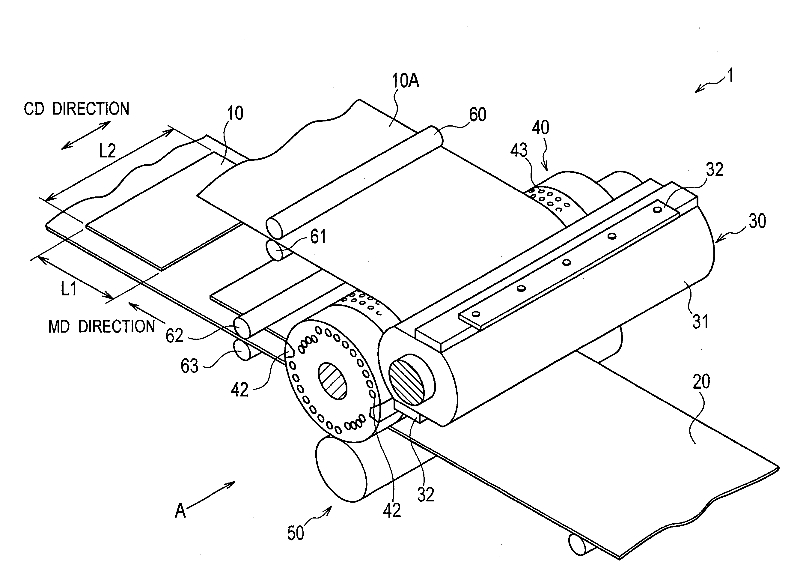
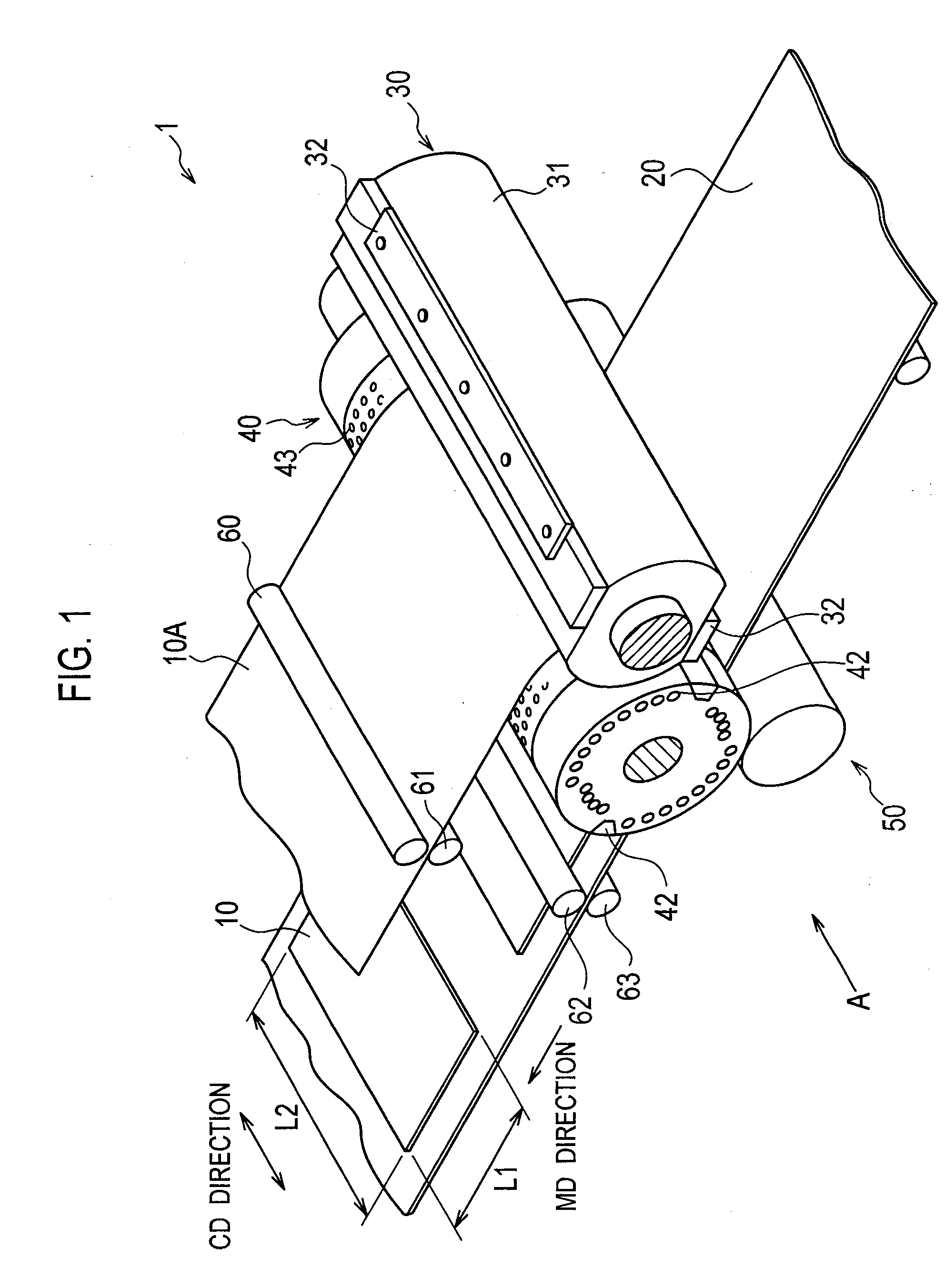
Intermittent cutting transferring device
a transfer device and intermittent technology, applied in the field of intermittent cutting transfer devices, can solve the problems of low rigidity and resilience of film sheets, and conventional intermittent cutting transfer devices are not capable of smoothing out so as to achieve easy uniform holding, suppress the formation of a crease in the continuum of film sheets 10a, and improve the effect of rigidity
- Summary
- Abstract
- Description
- Claims
- Application Information
AI Technical Summary
Benefits of technology
Problems solved by technology
Method used
Image

Examples
modified example
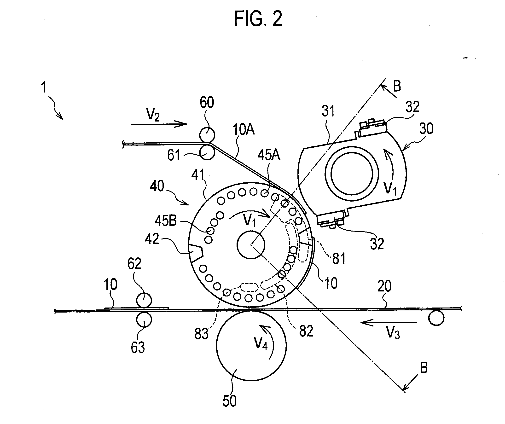
[0077]It has been described that the suction region 41A-1 according to the embodiment described above is provided in the roll width direction, but it may be modified as follows. Note that the same portions as those in the intermittent cutting transferring device 1 (lower blade roll 40) according to the embodiment described above are denoted by the same reference numerals, and differing portions will mainly be described.
example 1
(1) Modified Example 1
[0078]FIG. 8 is a development view showing the lower blade roll 40 according to Modified Example 1. As shown in FIG. 8, the suction region 41A-1 is provided to be symmetrical with respect to a center line (CL) passing through the center of the roll width direction as the reference. Note that the center line (CL) does not necessarily need to be the center of the roll width direction as long as it is the center of the cut film sheet 10 (continuum of film sheet 10A) in the CD direction, and it is needless to say that it may be the center between the pair of frames 71A and 71B, for example.
[0079]Specifically, the suction region 41A-1 is configured of a width direction region 411 in the roll width direction and inclined regions 412A and 412B located in end sections of the width direction region 411 and inclined to the roll width direction.
[0080]The inclined regions 412A and 412B are inclined to have a wider distance therebetween to a direction opposite to the roll r...
example 2
(2) Modified Example 2
[0083]FIG. 9 is a development view showing the lower blade roll 40 according to Modified Example 2. As shown in FIG. 9, the suction region 41A-1 is provided to be symmetrical with respect to the center line (CL) as the reference.
[0084]Specifically, the suction region 41A-1 is configured of a center area C provided on the center line (CL) and an outside region S provided on the outside of the center area C in the roll width direction.
[0085]The center area C is configured of a width direction region 411A in the roll width direction and inclined regions 412A and 412B respectively located in end sections of the width direction region 411A and inclined to the roll width direction.
[0086]The outside region S is configured of width direction regions 411B and 411C in the roll width direction and inclined regions 412C and 412D located in end sections of the width direction regions 411B and 411C on the outside in the roll width direction and inclined to the roll width dir...
PUM
| Property | Measurement | Unit |
|---|---|---|
| Current | aaaaa | aaaaa |
| Current | aaaaa | aaaaa |
| Diameter | aaaaa | aaaaa |
Abstract
Description
Claims
Application Information