Heating Medium Supply System, Integrated Solar Combined Cycle Electric Power Generation System and Method of Controlling These Systems

Inactive Publication Date: 2009-12-31
KAWASAKI HEAVY IND LTD
View PDF11 Cites 74 Cited by
  • Summary
  • Abstract
  • Description
  • Claims
  • Application Information

AI Technical Summary

Benefits of technology

[0054]According to the present invention, even when a heating medium to be supplied to a heat exchanging device fluctuates in its temperature in such a system as a solar thermal electric power generation system, it is possible to relieve a thermal influence upon the heat exchanging device resulting from a steep temperature rise due to such a temperature fluctuation. Also, even when the supply flow rate

Problems solved by technology

Therefore, electric power generation cannot continue day and night.
Irrespective of whether or not the solar thermal electric power generation system is the integrated solar combined cycle electric power generation system, there exists an unavoidable problem.
This problem is associated with the condition of solar radiation onto the surface of the Earth incidentally changing and fluctuating (with time) during daytime.
Since such a fluctuation occurs according to nature, it is difficult to predict accurately the time at which the fluctuation occurs and the degree of the fluctuation.
With the integrated solar combined cycle electric power generation system according to the European Patent Laid-Open Publication No. 0750730, the condition of steam to

Method used


Image

  • Heating Medium Supply System, Integrated Solar Combined Cycle Electric Power Generation System and Method of Controlling These Systems
  • Heating Medium Supply System, Integrated Solar Combined Cycle Electric Power Generation System and Method of Controlling These Systems
  • Heating Medium Supply System, Integrated Solar Combined Cycle Electric Power Generation System and Method of Controlling These Systems

Examples


Embodiment Construction

[0061]Embodiments of an integrated solar combined cycle electric power generation system, a heating medium supply system, a heating medium flow rate controlling method and a steam flow rate controlling method according to the present invention will be described with reference to the attached drawings.

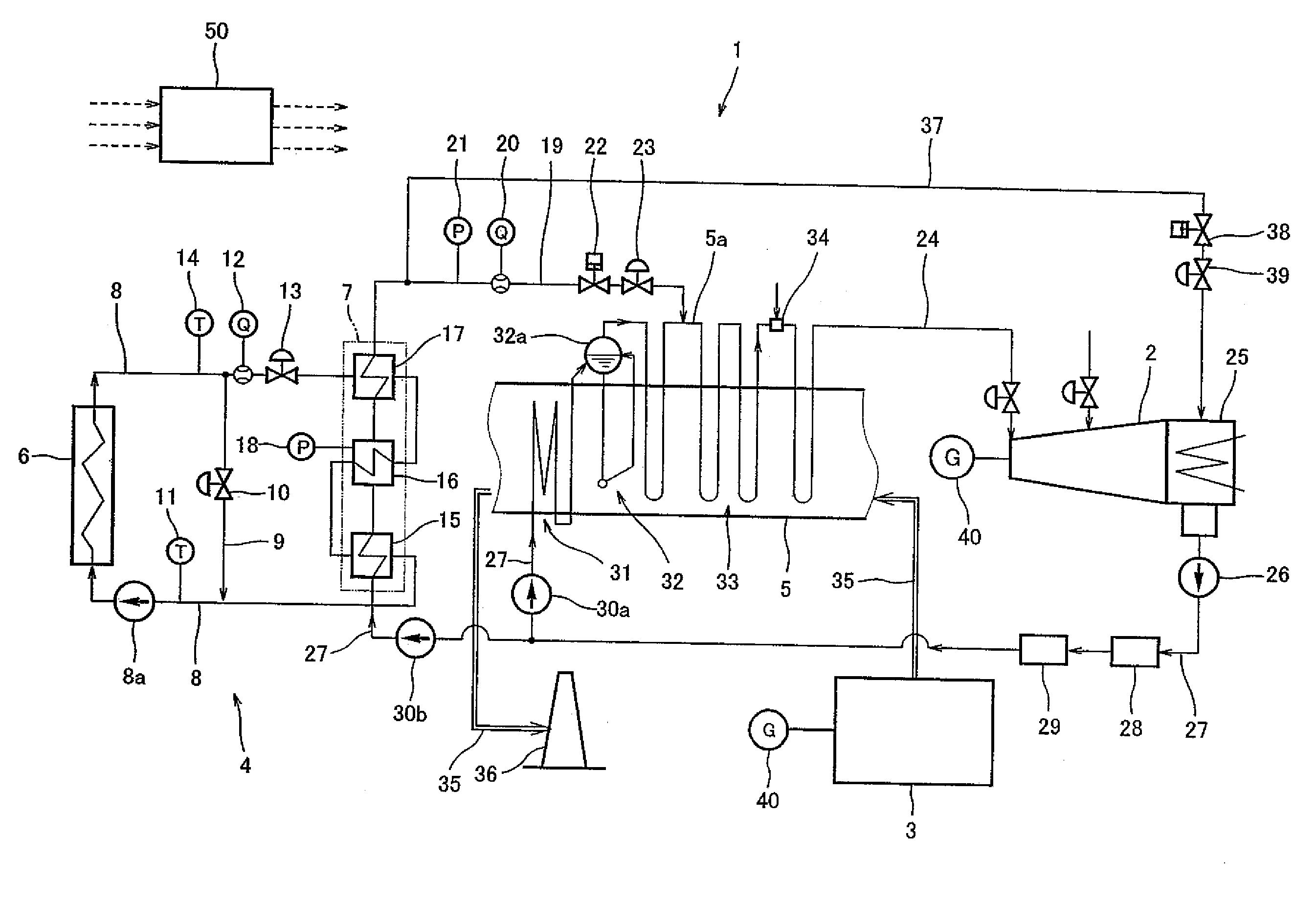
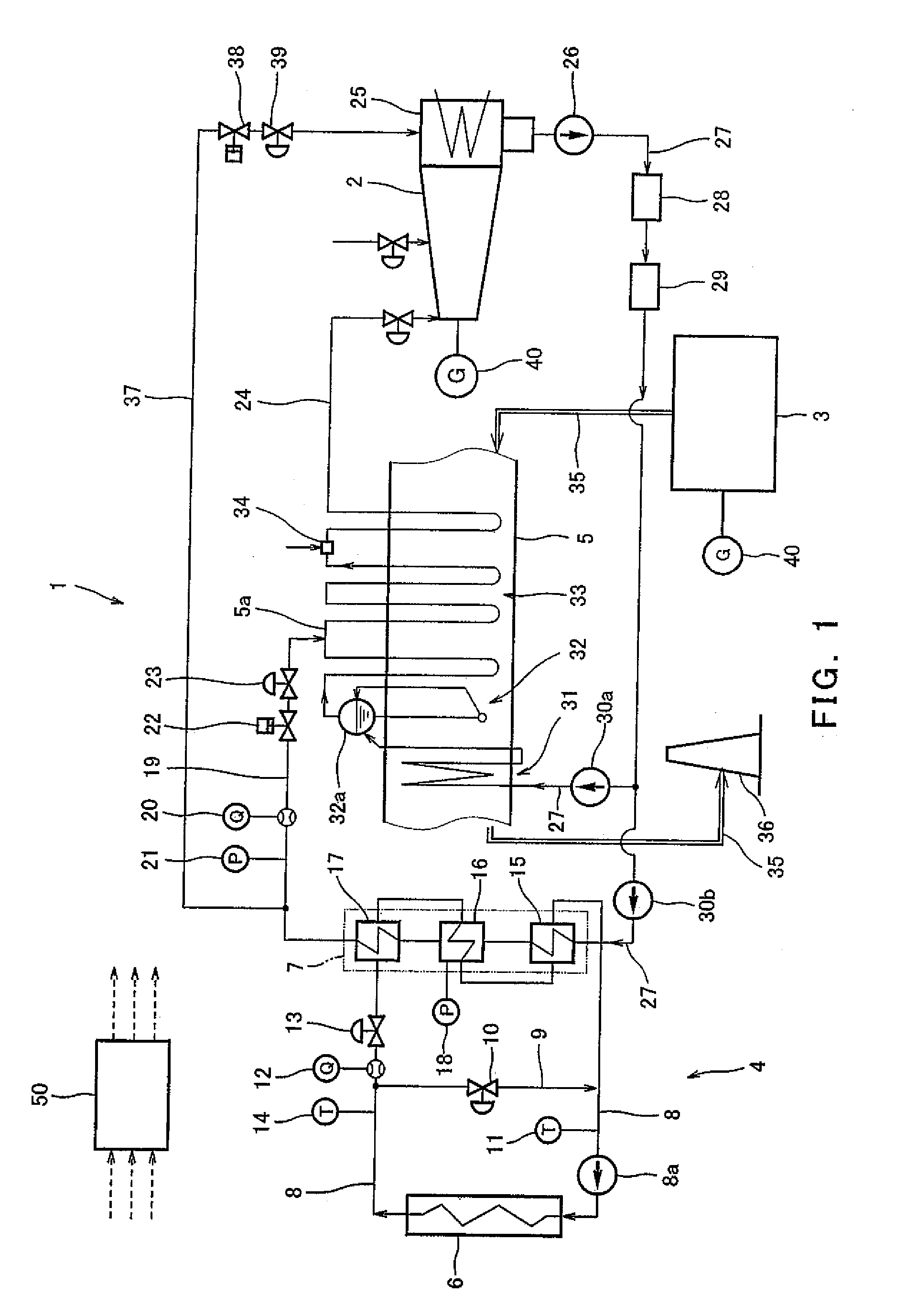
[0062]FIG. 1 illustrates an integrated solar combined cycle electric power generation system 1 in which a gas turbine electric power generation system using a gas turbine 3 driven by combusting any one of various gas or liquid fuels such as natural gas and a steam turbine electric power generation system using a steam turbine 2 driven by steam generated from solar heat as well as waste heat of the gas turbine 3 are combined together. The steam turbine 2 and the gas turbine 3 are coupled to respective electricity generators 40. In the electric power generation system 1, steam to be supplied to the steam turbine 2 is generated by a heat exchanging device 7 included in a system 4 configure...


PUM


Abstract

A heating medium supply system (4) is provided which, even when a temperature fluctuation of a heating medium occurs continuously, is capable of relieving a bad thermal influence upon a heat exchanging device due to the temperature fluctuation. The heating medium supply system (4) includes: a heating system (6) configured to heat a liquid heating medium by sunlight; a heat exchanging device (7) configured to heat feedwater by means of the heating medium supplied thereto from the heating system (6); heating medium supply piping (8) for circulating the heating medium to the heating system (6) and to the heat exchanging device (7); a heating medium temperature detecting device (14), a heating medium flow rate detecting device (12) and a first heating medium flow control valve (13), which are provided on the heating medium supply piping (8) at respective locations between an outlet of the heating system (6) and an inlet of the heat exchanging device (7); and a control device (50) capable of calculating a value of supply thermal energy from results of detections by the heating medium temperature detecting device (14) and the heating medium flow rate detecting device (12) and controlling an operation of the heating medium flow control valve (13) based on the value of supply thermal energy thus calculated.

Description

TECHNICAL FIELD[0001]The present invention relates to a heating medium supply system, an integrated solar combined cycle electric power generation system and a method of controlling a fluid in these systems. More specifically, the present invention relates to: a solar thermal electric power generation system configured to generate electric power by driving a steam turbine with the use of steam generated by means of a heating medium having collected solar thermal energy therein and steam generated by a waste heat recovery boiler; a heating medium supply system for generating steam to be supplied to various steam-using systems including such an electric power generation system; and flow rate controls over the heating medium and steam used in these systems.BACKGROUND ART[0002]A conventional solar thermal electric power generation system 101 shown in FIG. 4 has a configuration wherein: sunlight is collected by means of a concentrating type heat collecting unit (hereinafter will be refer...

Claims


Application Information

Patent Timeline
IPC IPC(8): F24J2/40F24S90/00
CPCF01K3/18F02C1/05F02C6/18F03G6/003Y02E20/16F01K13/00F01K23/101Y02E10/46
Inventor KOKETSU, MASAHIKOOTA, HIDEAKI
Owner KAWASAKI HEAVY IND LTD
Why Eureka
Try Eureka