Rocket rig drilling apparatus

a drilling apparatus and rock rig technology, applied in the direction of drilling rods, drilling pipes, rotary drilling, etc., can solve the problems of inconvenient transportation, high cost of assembling and use, and complex prior art elevated floor structures, etc., and achieves convenient rig up and down and easy transportation

Active Publication Date: 2009-12-31
VORA THEODORE CHEN
View PDF3 Cites 40 Cited by
  • Summary
  • Abstract
  • Description
  • Claims
  • Application Information

AI Technical Summary

Benefits of technology

[0007]The present invention is a well drilling apparatus that is modular, easy to rig up and down and easy to transport. This well drilling apparatus has a pre-assembled modular substructure, at least one pre-assembled modular mast intermediate section, and a pre-assembled modular top mast section, which includes a traveling block and a crown block as a unit. The substructure comprises a mast starter section which has its front legs pivotally mounted to the substructure at the front leg mounts, an elevatable drill floor which is pivotally connected to the substructure via supporting legs, at least one dog tail for pivotally raising the assembled mast to its vertical operating position, and a mast assembly raising system. The mast intermediate sections and the top mast section are assembled at ground level, without requiring the use of a crane. Once the mast is assembled at ground level, the mast assembly raising system raises the mast to its vertical operating position while simultaneously raising the elevatable drill floor. The elevatable drill floor remains in a substantially horizontal position during the entire raising or lowering process.

Problems solved by technology

In order to accommodate the need for an elevated equipment floor, numerous structures have evolved, but have proven to be deficient in many ways.
Most particularly, prior art elevated floor structures have proven to be relatively complex and time consuming to assemble at the drilling site, and, for this reason, are expensive to assemble and use.
In many such prior art structures, the elevated floor and then the mast must be constructed and connected together in, essentially, a piece-by-piece operation, very often requiring the use of a crane which thereby increases the expense.
Further, when structures are finally erected, the rigging or outfitting of them must be carried out at the elevated level further requiring the use of a crane and additionally complicating the rigging process.
This arrangement, therefore, produces a complex arrangement for constructing the elevated floor, as well as an expensive rigging operation.

Method used


Image

  • Rocket rig drilling apparatus
  • Rocket rig drilling apparatus
  • Rocket rig drilling apparatus

Examples


Embodiment Construction

[0024]The following discussion is presented to enable a person skilled in the art to make and use the invention. The general principles described herein may be applied to embodiments and applications other than those detailed below without departing from the spirit and scope of the present invention as defined by the appended claims. The present invention is not intended to be limited to the embodiments shown, but is to be accorded the widest scope consistent with the principles and features disclosed herein.

[0025]As such, those skilled in the art will appreciate that the conception, upon which this disclosure is based, may readily be utilized as a basis for the designing of other structures, methods, and devices for carrying out the several purposes of the present invention. It is important, therefore, that the claims be regarded as including such equivalent constructions insofar as they do not depart from the spirit and scope of the present invention.

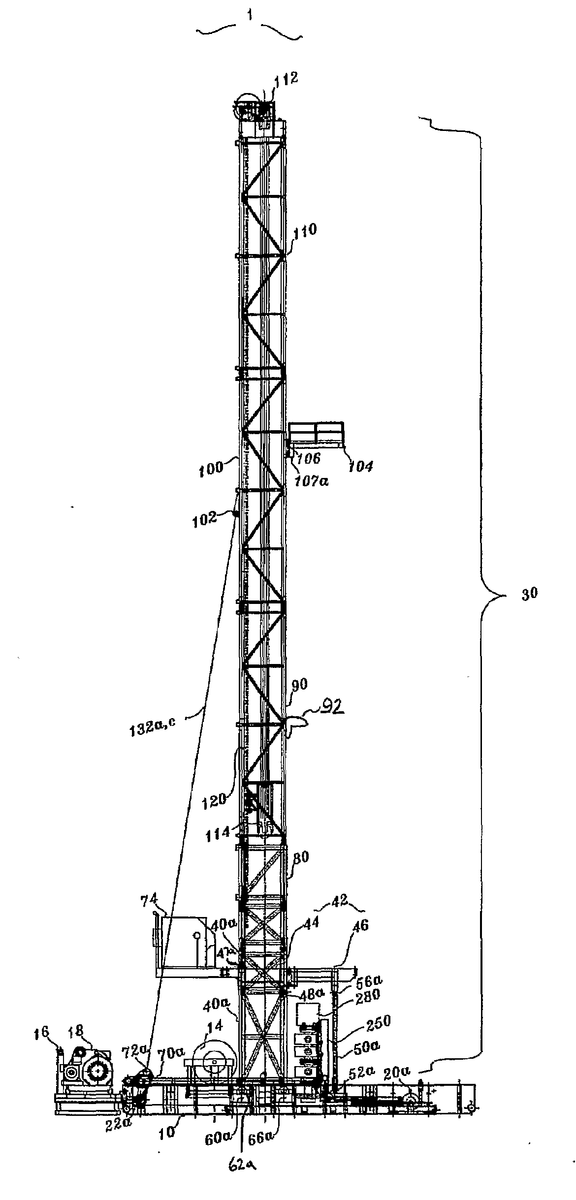
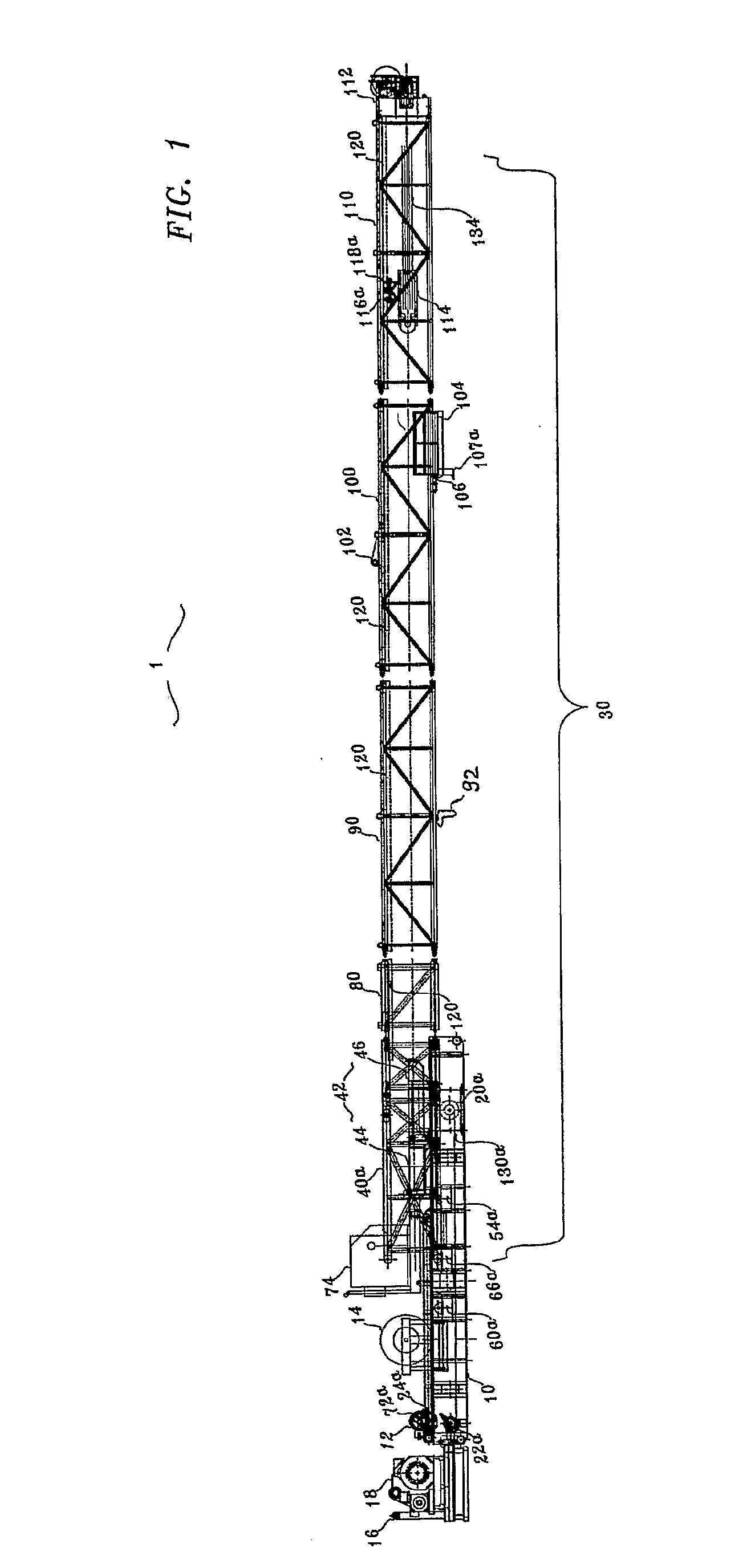
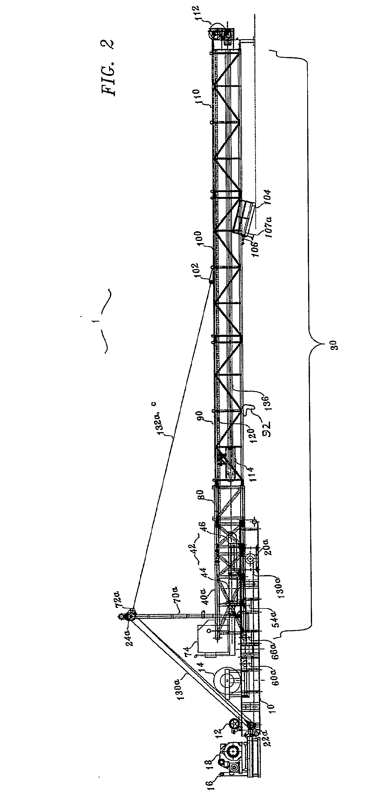
[0026]Referring to the drawing...


PUM


Abstract

A well drilling apparatus includes multiple, transportable, modular, pre-assembled sections which include a substructure and multiple mast sections. These pre-assembled sections allow for a quicker complete rig-up of the well drilling apparatus at ground level in a horizontal direction, without the use of a crane. Once the assembly has been completed at ground level, the mast is raised to its vertical operating position via mechanisms for raising and lowering dog tails. During transport, the guide rails are built-in to the mast sections and the crown block is attached to the traveling block, thereby facilitating the rigging-up process. The mast may be lowered after the drilling operation has been accomplished without interfering with any blow-out preventer devices that may have been placed on the wellhead while the structure was at its raised operational level.

Description

[0001]This application claims the benefit of both U.S. Provisional Application No. 60 / 708,478, filed Aug. 16, 2005, and U.S. Provisional Application No. 60 / 771,561, filed Feb. 8, 2006.FIELD OF THE INVENTION[0002]The present invention relates generally to a well drilling apparatus and more particularly to a well drilling apparatus that can be entirely assembled horizontally at ground level and raised to a vertical operating position for drilling oil and gas wells or the like. The well drilling apparatus is modular and can be relocated easily from one site to another without much disassembling.BACKGROUND[0003]For many drilling operations, it is necessary to drill relatively deep wells, thereby requiring longer drill strings and larger traveling blocks. These longer drill strings and larger traveling blocks, in turn, require the use of greater mast heights. To accommodate this requirement, usually mounted drawworks and other drilling equipment are placed on an elevated equipment floor,...

Claims


Application Information

Patent Timeline
Patent Type & Authority Applications(United States)
IPC IPC(8): E21B15/00E04H12/34E21B7/02
CPCE21B19/00E21B15/00
Inventor VORA, THEODORE CHEN
Owner VORA THEODORE CHEN
Why Eureka
Try Eureka