

Small-sized motor
- Summary
- Abstract
- Description
- Claims
- Application Information
AI Technical Summary
Benefits of technology
Problems solved by technology
Method used
Image

Examples
Embodiment Construction
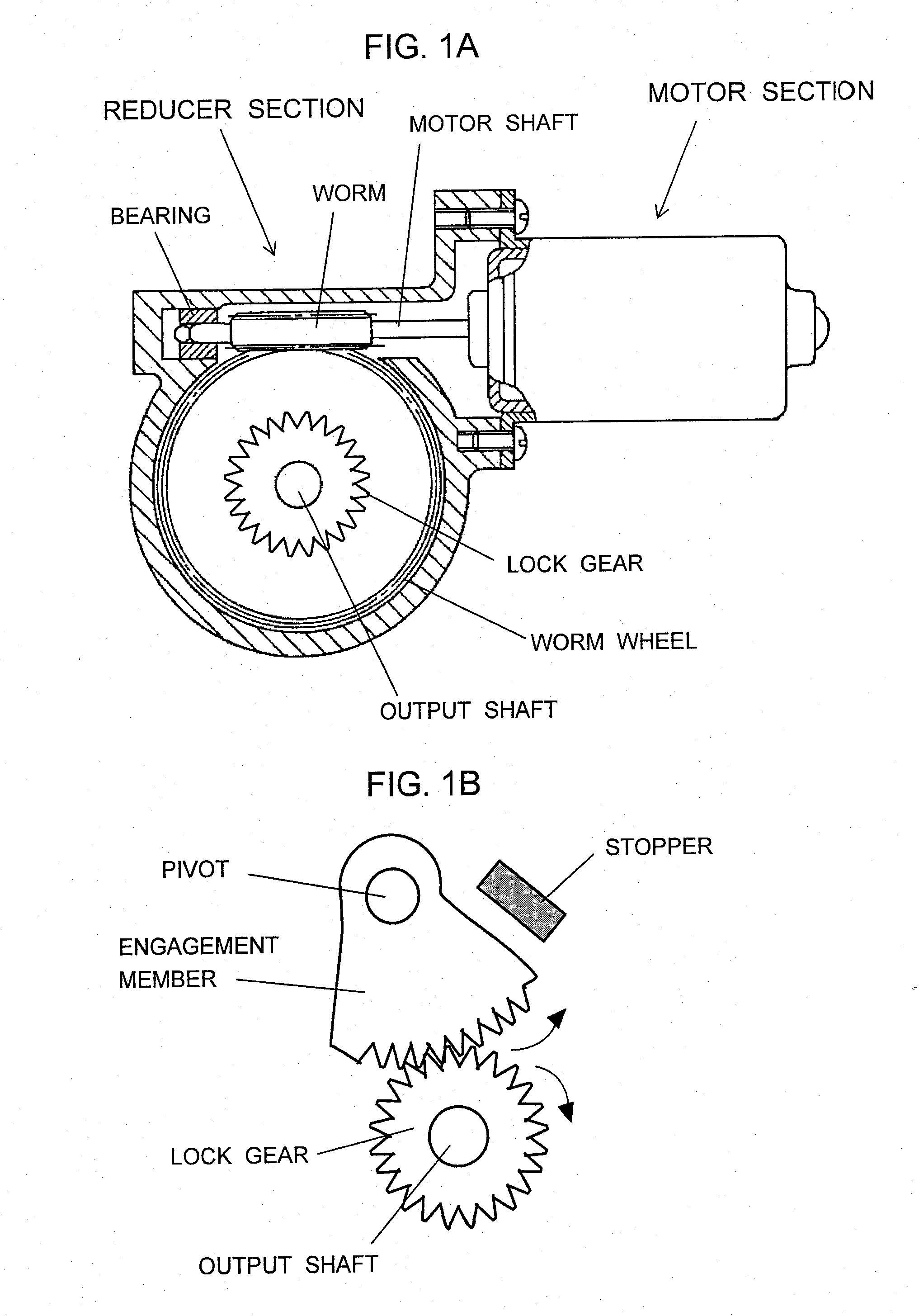
[0019]FIGS. 1A and 1B are a pair of views showing a mechanical unit having a stopper mechanism to which the present invention is applicable, wherein FIG. 1A is an overall view of a small-sized motor, showing, in section, a worm reducer section, and FIG. 1A is a sectional view showing, on an enlarged scale, the stopper mechanism section. In FIG. 1A, a motor section is attached to the reducer section. A projecting end portion of a motor shaft is supported by a bearing of the reducer section. A worm is fixed on the motor shaft. A worm wheel is meshed with the worm. A drive torque output from the motor section is transmitted from the motor shaft to the worm. In the reducer section, the drive torque is transmitted from the worm to the worm wheel and is then output from the output shaft.
[0020]In the illustrated small-sized motor, the stopper mechanism includes a lock gear, which is fixed on the output shaft and rotates together with the output shaft; an engagement member, which has gear t...
PUM
 Abstract
Description
Claims
Application Information