
Transmission of utility data

a utility data and transmission method technology, applied in the field of transmission methods and systems for utility data, can solve the problems of increasing cost and convenience, neither method is amenable to real-time meter reading, and the current limited use of individual users' home-based automated networks

Active Publication Date: 2009-12-31
QWEST
View PDF13 Cites 43 Cited by
  • Summary
  • Abstract
  • Description
  • Claims
  • Application Information

AI Technical Summary

Benefits of technology

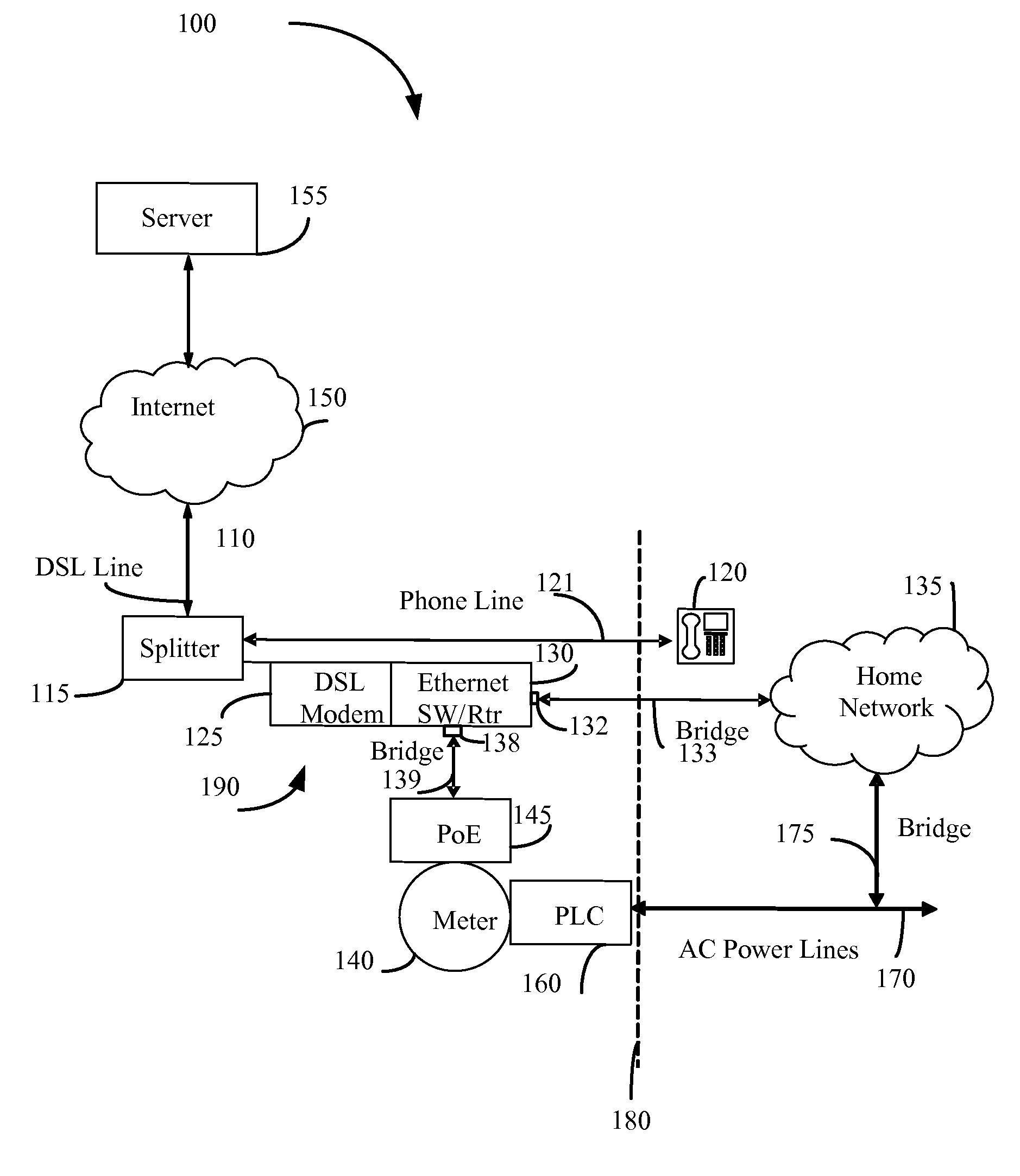
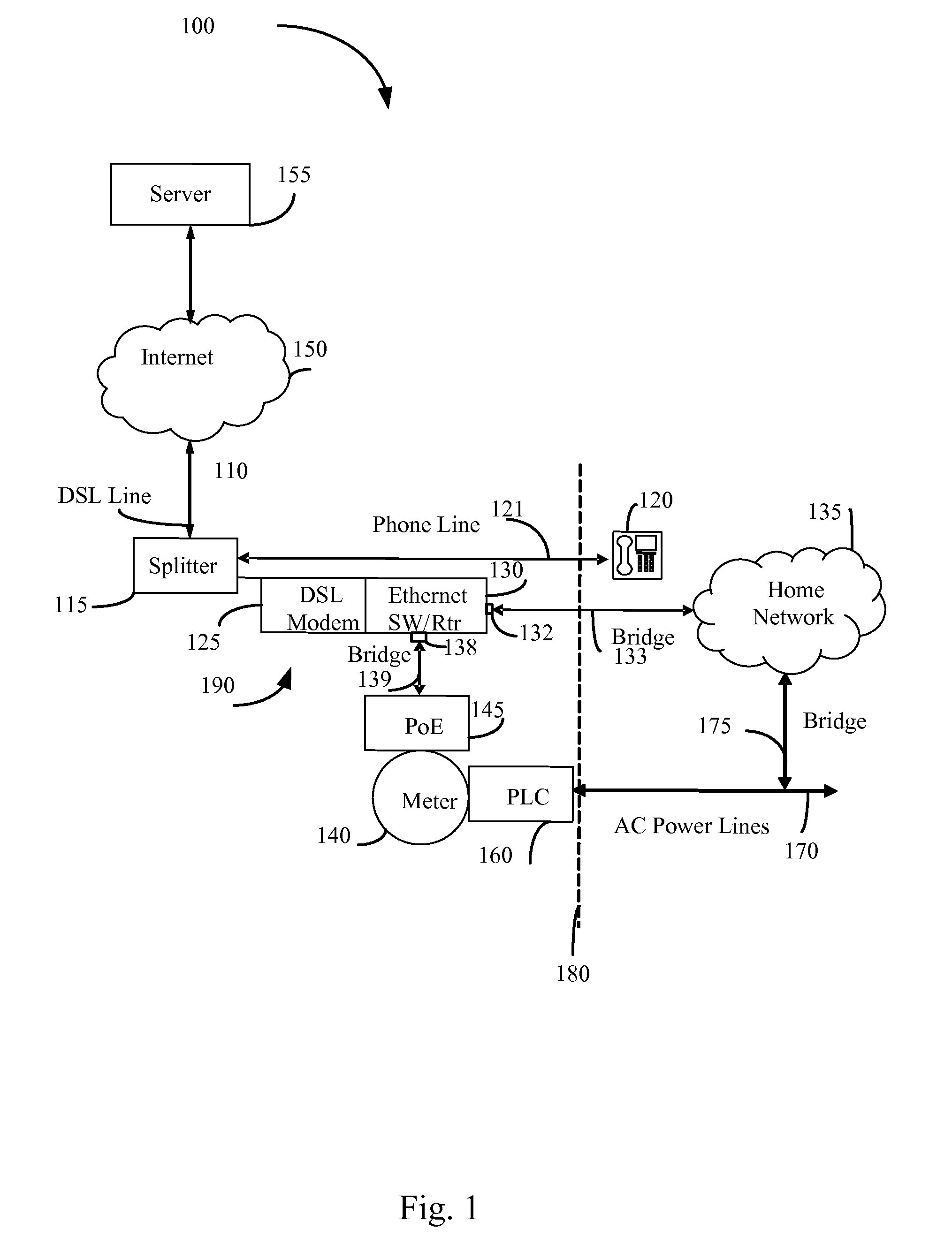
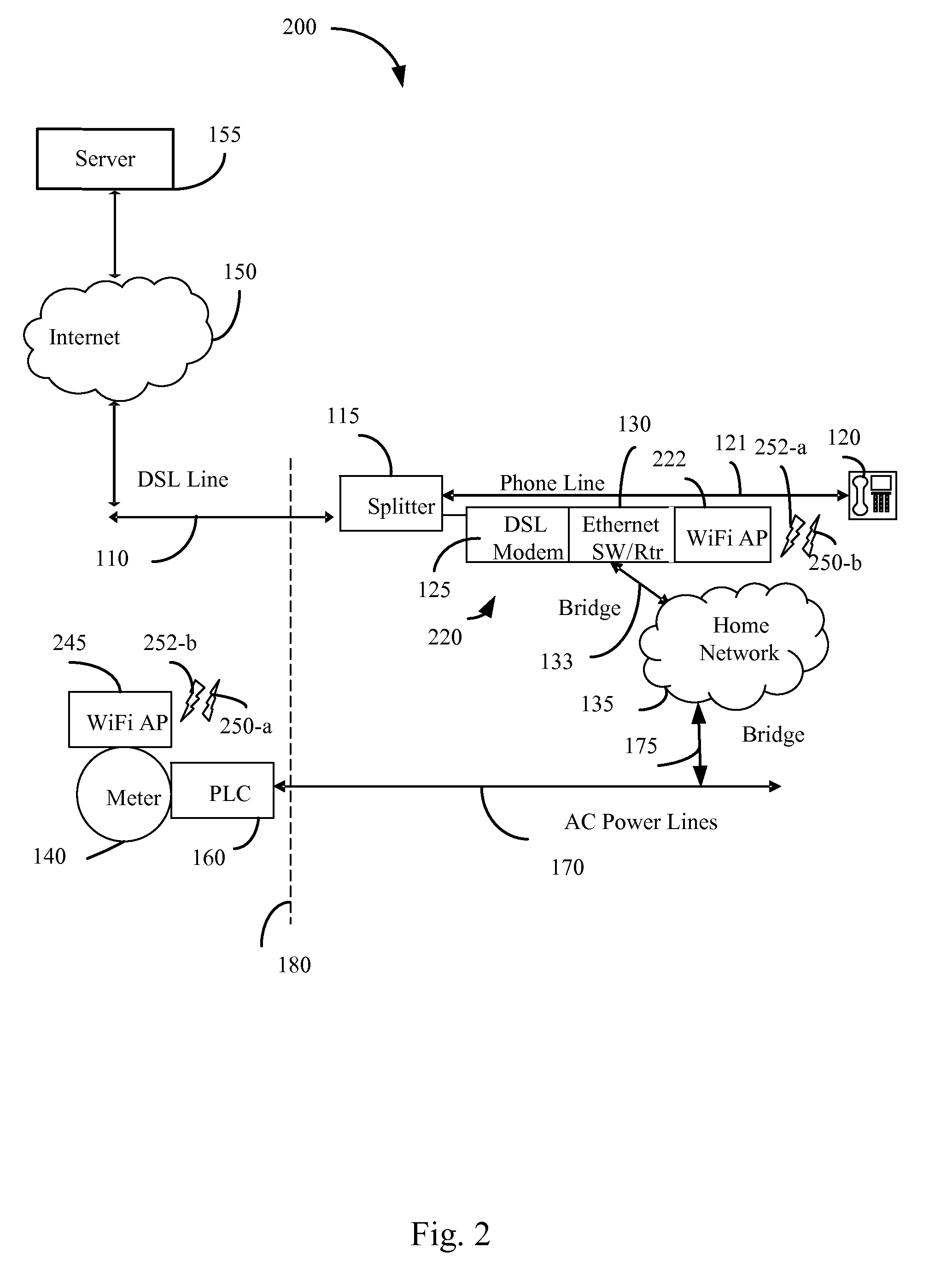
[0006]Certain embodiments thus provide tools and techniques allowing utility providers to collect meter readings without a technician having to visit a customer premises, along with providing centralized monitoring, managing, and control of device usage in a home. Data pertaining to a meter reading may be transmitted from a utility meter to an access point of a public broadband network, in some cases without any human intervention. The access point may include a modem, such as a digital subscriber line (“DSL”) modem (to name but one example), which may modulate the data pertaining to the meter reading. The modulated data may then be transmitted securely through a public switched telephone network (“PSTN”) to the Internet. The data may then be received by the utility provider via the Internet.

Problems solved by technology

Both of these techniques require substantial human interaction, resulting in increased cost and decreased convenience.
Moreover, neither of these methods is amenable to real-time meter reading.
However, these technologies currently are limited to individual users implementing their own Home Automated Networks using private Home Networking mechanisms such as X10, Z-Wave, and Zigbee.
To date, however, such technologies have been implemented on an individual scale and cannot benefit from centralized monitoring and / or management capabilities; further, because there is no interface between such technologies and current information about utility rates, the potential benefits of such technologies have not been maximized.

Method used


Image

  • Transmission of utility data
  • Transmission of utility data
  • Transmission of utility data

Examples


Embodiment Construction

[0024]The ensuing description provides exemplary embodiments only, and is not intended to limit the scope, applicability or configuration of the disclosure. Rather, the ensuing description of the exemplary embodiments will provide those skilled in the art with an enabling description for implementing one or more exemplary embodiments, it being understood that various changes may be made in the function and arrangement of elements without departing from the spirit and scope of the invention as set forth in the appended claims. Several embodiments are described herein, and while various features are ascribed to different embodiments, it should be appreciated that the features described with respect to one embodiment may be incorporated within other embodiments as well. By the same token, however, no single feature or features of any described embodiment should be considered essential to every embodiment of the invention, as other embodiments of the invention may omit such features.

[00...


PUM


Abstract

Certain embodiments are directed at methods and systems for transmitting utility usage data using a public switched telephone network (“PSTN”). The methods and systems may include collecting utility usage data pertaining to a customer premises with a utility meter at the customer premises. The utility usage data may be transmitted automatically from the utility meter to an access point of a public broadband network. The utility usage data may be received at the access point. A digital subscriber line (“DSL”) modem in communication with the access point may modulate the utility usage data at the access point. The utility usage data may be transmitted securely through the public switched telephone network to an Internet point of presence. The utility usage data may be received at the Internet point of presence. The utility usage data may be transmitted from the Internet point of presence to a utility provider via the Internet.

Description

CROSS-REFERENCES TO RELATED APPLICATIONS[0001]This application is a continuation-in-part of co-pending U.S. patent application Ser. No. 12 / 409,975, filed Mar. 24, 2009 by Casey et al. and entitled “Transmitting Utility Usage Data Via A Network Interface Device” (Attorney Docket no. 020366-090110US, referred to herein as the “Casey Application”). The Casey application is a continuation of U.S. patent application Ser. No. 10 / 377,280, filed Feb. 27, 2003 by Phillips et al. and entitled “ADSL / DBS NETWORK INTERFACE DEVICE AND METHODS AND SYSTEMS FOR USING THE SAME (the “'280 application”). The '280 application is a continuation-in-part application of U.S. patent application Ser. No. 10 / 356,364, entitled “PACKET NETWORK INTERFACE DEVICE AND SYSTEMS AND METHODS FOR ITS USE,” filed Jan. 31, 2003 by Bruce A. Phillips et al. (Attorney Docket No. 020366-087700US); is a continuation-in-part application of U.S. patent application Ser. No. 10 / 356,688, entitled “SYSTEMS, METHODS AND APPARATUS FOR ...

Claims


Application Information

Patent Timeline
Patent Type & Authority Applications(United States)
IPC IPC(8): G08C15/06
CPCG01D4/004Y04S20/42H04B2203/5433H04B2203/5445H04B2203/5458H04L12/2825H04L12/2856H04L29/06027H04L2012/2843H04M11/002H04M11/062H04N7/173H04N21/4622H04N21/6125Y02B90/242Y04S20/322H04L65/1026H04L65/1036H04L67/12Y02B90/246H04B3/546Y02B90/20Y04S20/30H04L65/1101
Inventor COOK, CHARLES I.DHALIWAL, RONNIE S.CASEY, STEVEN M.
Owner QWEST
Learn More