Antenna arrangement

a technology for antenna elements and antenna supports, applied in antenna supports/mountings, multi-port networks, transmission, etc., can solve the problems of dramatically affecting the performance of antenna elements, difficult problem in designing radio frequency antenna elements, and difficult problem in designing multi-band radio frequency antenna elements

Active Publication Date: 2009-12-31
NOKIA TECHNOLOGLES OY
View PDF13 Cites 21 Cited by
  • Summary
  • Abstract
  • Description
  • Claims
  • Application Information

AI Technical Summary

Benefits of technology

[0024]According to some, but not necessarily all, examples of the invention there is provided an antenna arrangement for radio communication in a first radio communication band and for communication in a second radio communication band comprising: an antenna element having a feed for connection to radio frequency circuitry; and a load connected to the feed and comprising a capacitor, an inductor and one or more additional reactive comp

Problems solved by technology

One problem associated with radio frequency technology is that at least one antenna element is required to be able to transmit radio frequency signals and/or to receive radio frequency signals.
It is a difficult problem to design a radio frequency antenna element that has an acceptable efficiency in a frequency band of interest and which is also of a small size.
Furthermore, the size of a separation of an

Method used


Image

  • Antenna arrangement
  • Antenna arrangement
  • Antenna arrangement

Examples


Embodiment Construction

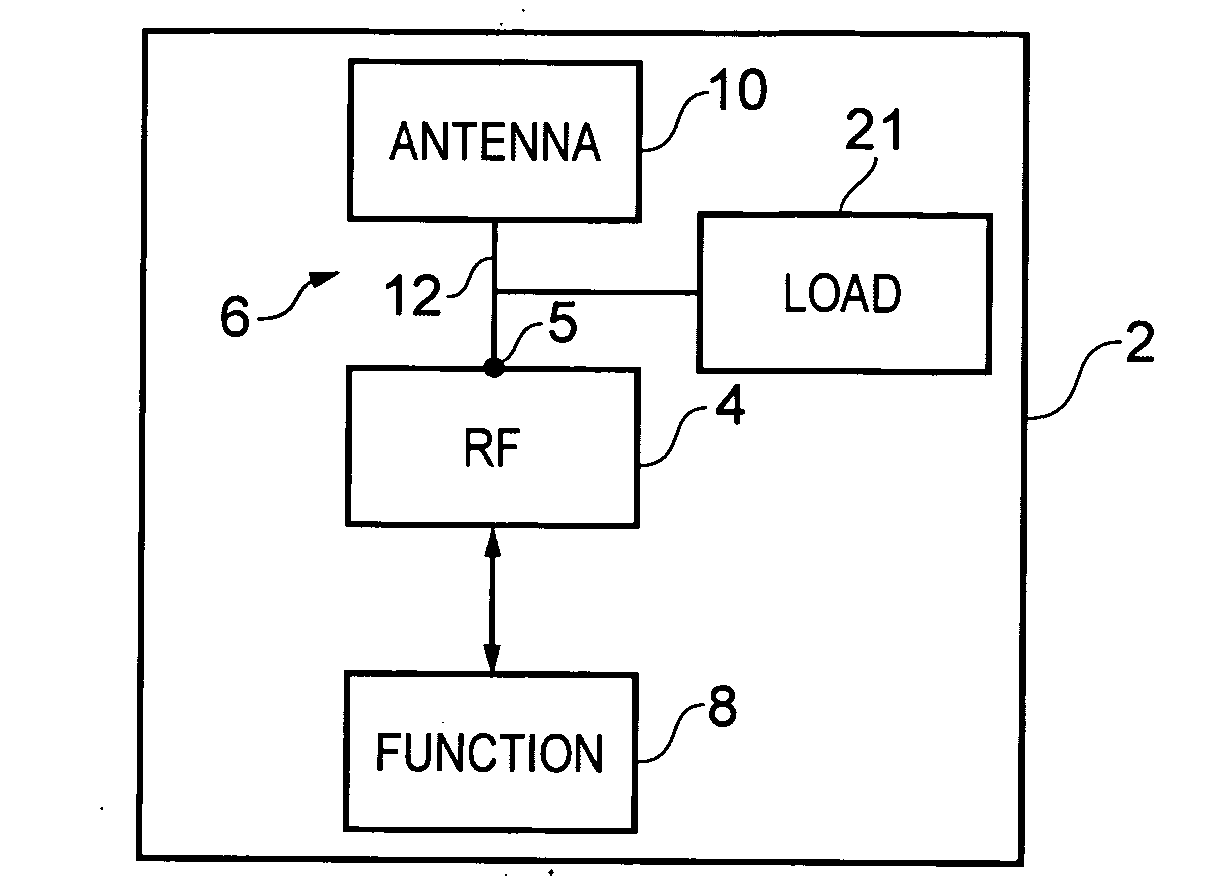
[0038]FIG. 1 schematically illustrates an apparatus 2 that is suitable for radio communications using radio frequency (RF) technology. The apparatus 2 in this example, comprises functional circuitry 8 which provides data to RF circuitry 4 and / or receives data from RF circuitry 4 and an antenna arrangement 6 connected to the RF circuitry 4. The antenna arrangement 6 includes an antenna element 10 and a load 21.

[0039]The apparatus 2 may be any suitable device such as network equipment or portable electronic devices like a mobile terminal in a cellular communications network or, a hand-portable device such as a mobile cellular telephone, personal digital assistant, gaming device, music player, personal computer, that enables the device to communicate using RF technology.

[0040]Although in the following paragraphs, the RF technology is described in relation to a mobile cellular terminal for use in a cellular communications network, embodiments of the invention may find application in oth...


PUM


Abstract

An antenna arrangement for radio communication in a first radio communication band and for communication in a second radio communication band including a multiple-resonance antenna element having a feed for connection to radio frequency circuitry; and a load connected to the feed and comprising a plurality of reactive components including a first reactive component that controls the impedance of the load for the first radio communication band and a second reactive component, separate from the first reactive component, that controls the impedance of the load for the second radio communication band wherein the plurality of reactive components of the load are configured to provide an impedance that changes between being inductive at a first frequency in the first radio communication band to being capacitive at a second frequency in the first radio communication band and that changes between being inductive at a third frequency in the second radio communication band to being capacitive at a fourth frequency in the second radio communication band.

Description

FIELD OF THE INVENTION[0001]Embodiments of the present invention relate to an antenna arrangement. In particular, they relate to a low-profile antenna arrangement.BACKGROUND TO THE INVENTION[0002]It is generally desirable to make radio frequency technology more compact so that the devices carrying the technology can be made smaller or so that the technology can be integrated into devices that at present do not include the technology.[0003]One problem associated with radio frequency technology is that at least one antenna element is required to be able to transmit radio frequency signals and / or to receive radio frequency signals. It is a difficult problem to design a radio frequency antenna element that has an acceptable efficiency in a frequency band of interest and which is also of a small size.[0004]Performance of an antenna element is dependent upon the size of the antenna element as there is generally a relationship between the physical size of the antenna element and it's elect...

Claims


Application Information

Patent Timeline
IPC IPC(8): H01Q1/24H01Q9/00H01Q5/10H01Q5/335
CPCH01Q1/243H03H7/40H01Q5/335H04B1/0053H04B1/0458H04B1/18
Inventor XIE, WANBOHE, WEILIU, SHUAN, RONG BANG
Owner NOKIA TECHNOLOGLES OY
Why Eureka
Try Eureka