Antenna apparatus

a technology of antennas and antennas, applied in the field of antenna apparatuses, can solve the problems of large space occupied by electronic devices, inability to effectively prevent coupling effects, etc., and achieve the effect of reducing coupling effects and reducing distance between antennas

Inactive Publication Date: 2009-12-31
ASUSTEK COMPUTER INC
View PDF6 Cites 53 Cited by
  • Summary
  • Abstract
  • Description
  • Claims
  • Application Information

AI Technical Summary

Benefits of technology

[0009]In the invention, two ends of the conducting wire are electrically connected to the first planar antenna and the second planar antenna, respectively. Then, a current loop is form...

Problems solved by technology

This is not only unable to prevent the coupling effect eff...

Method used


Image

  • Antenna apparatus
  • Antenna apparatus
  • Antenna apparatus

Examples


Embodiment Construction

[0015]In the following embodiments, elements with the same or similar functions or structures are illustrated with the same symbols and names.

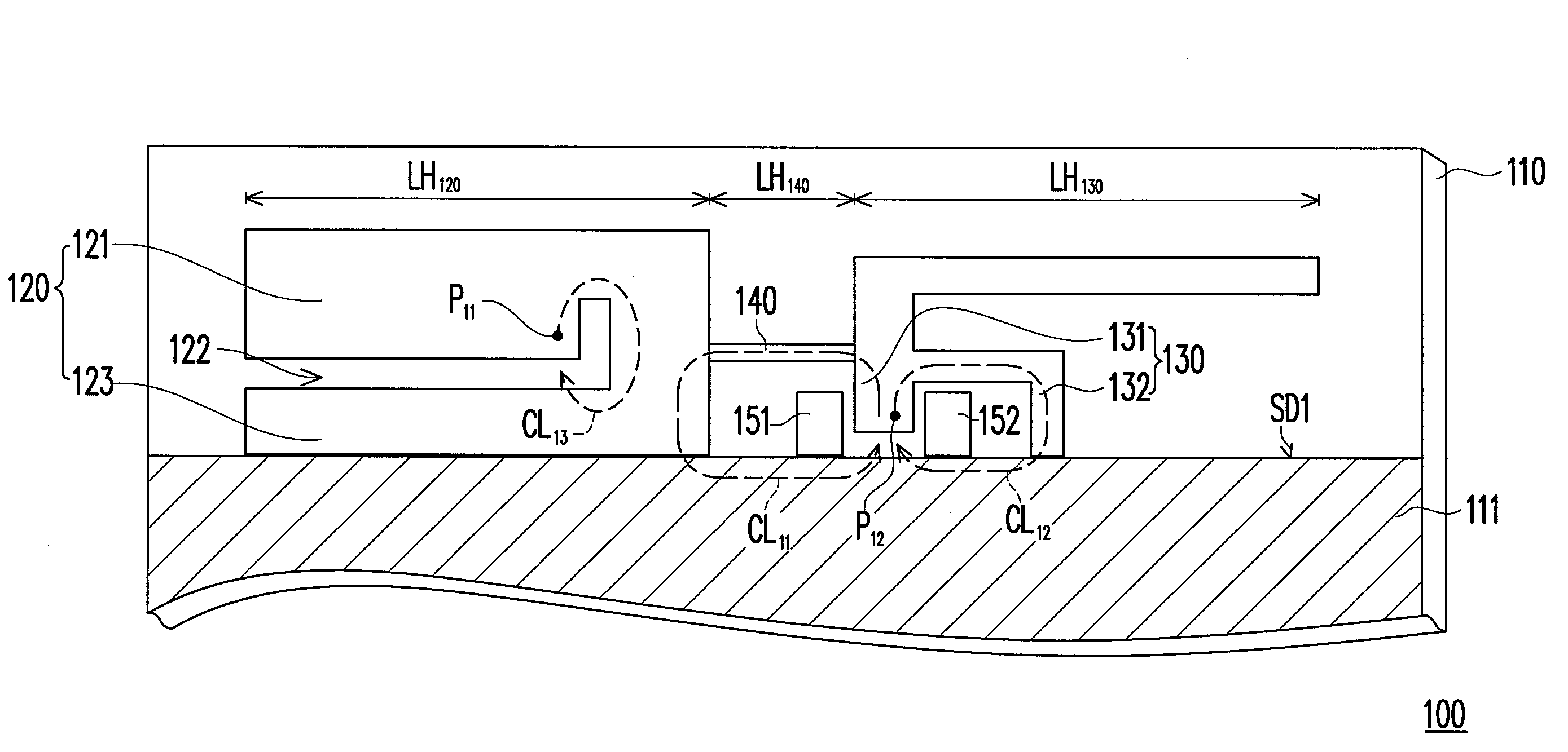
[0016]FIG. 1 is a schematic diagram showing the structure of an antenna apparatus in a first embodiment of the invention. As shown in FIG. 1, the antenna apparatus 100 includes a substrate 110, a first planar antenna 120, a second planar antenna 130 and a conducting wire 140. A metal layer 111 is disposed on the substrate 110, and the substrate 110 is, for example, a printed circuit board. In addition, the first planar antenna 120, the second planar antenna 130 and the conducting wire 140 are disposed on the substrate 110.

[0017]In the whole structure, the first planar antenna 120 and the second planar antenna 130 are arranged side by side along the side SD1 of the metal layer 111. In addition, the first planar antenna 120 and the second planar antenna 130 are electrically connected to the side SD1 of the metal layer 111. In another aspect, the...


PUM


Abstract

An antenna apparatus including a metal layer, a first planar antenna, a second planar antenna and a conducting wire is provided. The first planar antenna has a first ground terminal electrically connected to the metal layer. The second planar antenna has a second ground terminal electrically connected to the metal layer. The conducting wire is connected between the first planar antenna and the second planar antenna. In the whole operation, electromagnetic signals transmitted by the first planar antenna and the second planar antenna are in the same frequency band, and the coupling effect of the first planar antenna and the second planar antenna is reduced along with the formation of a current loop of the conducting wire.

Description

CROSS-REFERENCE TO RELATED APPLICATION[0001]This application claims the priority benefit of Taiwan application serial no. 97124265, filed on Jun. 27, 2008. The entirety of the above-mentioned patent application is hereby incorporated by reference herein and made a part of specification.BACKGROUND OF THE INVENTION[0002]1. Field of the Invention[0003]The invention relates to an antenna apparatus and, more particularly, to an antenna apparatus which may reduce the coupling effect using a conducting wire connected between two planar antennas.[0004]2. Description of the Related Art[0005]In recent years, to meet the users' growing demand for the connection between computers and various peripheral equipment or consumptive devices, electronic devices nowadays need various built-in wireless transmission functions such as the functions of the global positioning system (GPS), the communication system for mobile communications (GSM), the wireless local area network (WLAN), the wireless metropol...

Claims


Application Information

Patent Timeline
IPC IPC(8): H01Q1/38H01Q13/10
CPCH01Q1/243H01Q21/28H01Q9/42H01Q1/521
Inventor LAI, MING-IU
Owner ASUSTEK COMPUTER INC
Why Eureka
Try Eureka