Compact virtual display

a virtual display and compact technology, applied in the field of optical devices, can solve the problems of inconvenient long-time use, inability to simultaneously observe a projected image and a real environment, and the enlargement of the apparatus, so as to achieve significant durability, reduce weight, and reduce the effect of weigh

Inactive Publication Date: 2009-12-31
SAMSUNG ELECTRONICS CO LTD
View PDF11 Cites 82 Cited by
  • Summary
  • Abstract
  • Description
  • Claims
  • Application Information

AI Technical Summary

Benefits of technology

[0011]The present invention provides a compact virtual display that provides capability of simultaneously observing a virtual image, i.e. a projected image, and a real environment.
[0012]The present invention also provides a compact virtual display having small size, low weight, and significant durability.

Problems solved by technology

In more detail, to provide an acceptable dimension of a virtual image, a large numerical aperture is required, which leads to considerable enlargement of weight and size of the apparatuses, making them inconvenient for long-time usage.
Also, none of the above conventional inventions have the ability to simultaneously observe a projected image and a real environment.

Method used


Image

  • Compact virtual display
  • Compact virtual display
  • Compact virtual display

Examples


Embodiment Construction

[0035]Reference will now be made in detail to example embodiments, examples of which are illustrated in the accompanying drawings. However, the invention is not limited to the embodiments illustrated and provided herein; the provided embodiments herein are introduced to provide an understanding of the spirit of the invention. Like reference numerals denote like elements throughout. In the drawings, the thicknesses of layers regions and scale may be exaggerated for clarity.

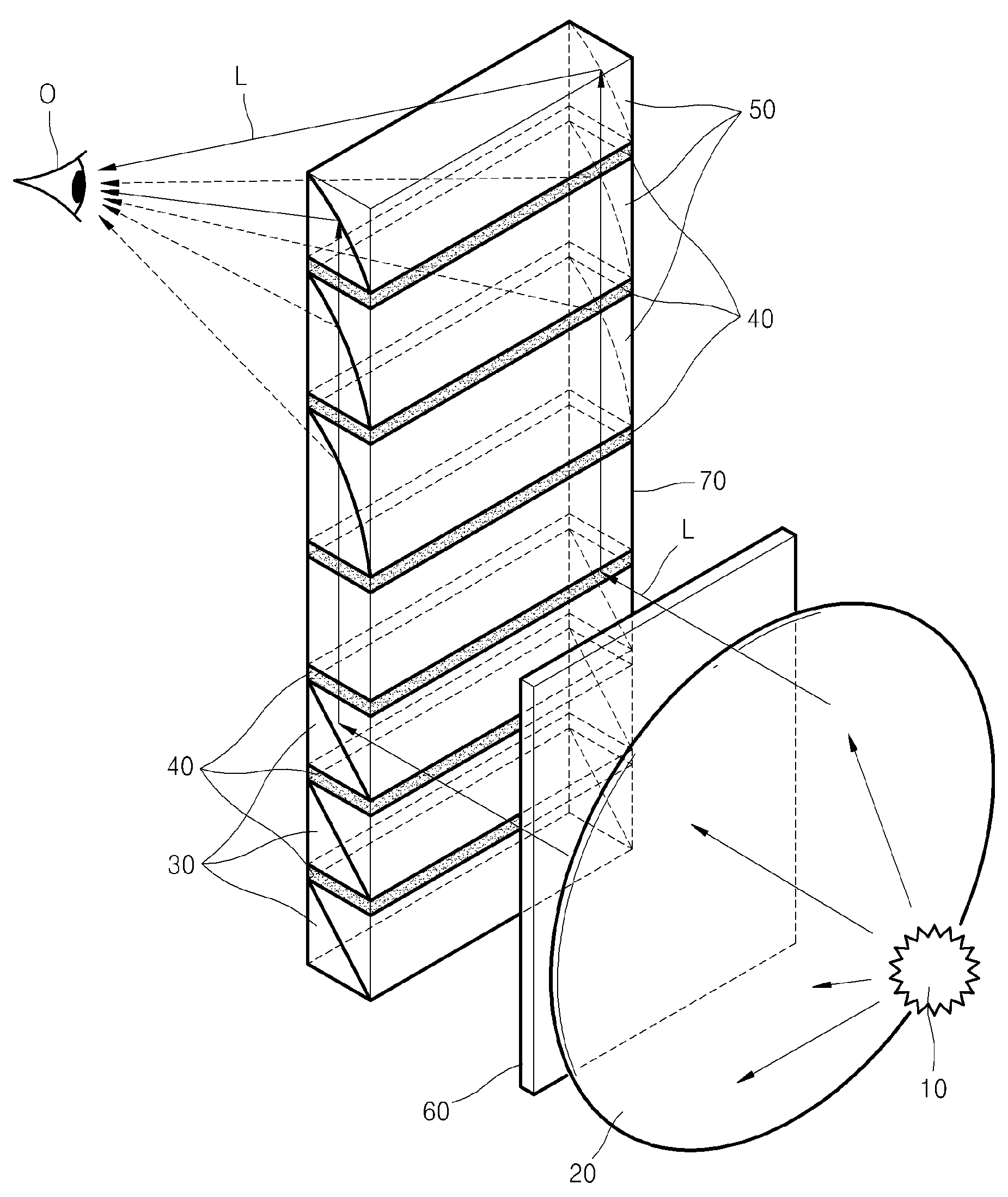
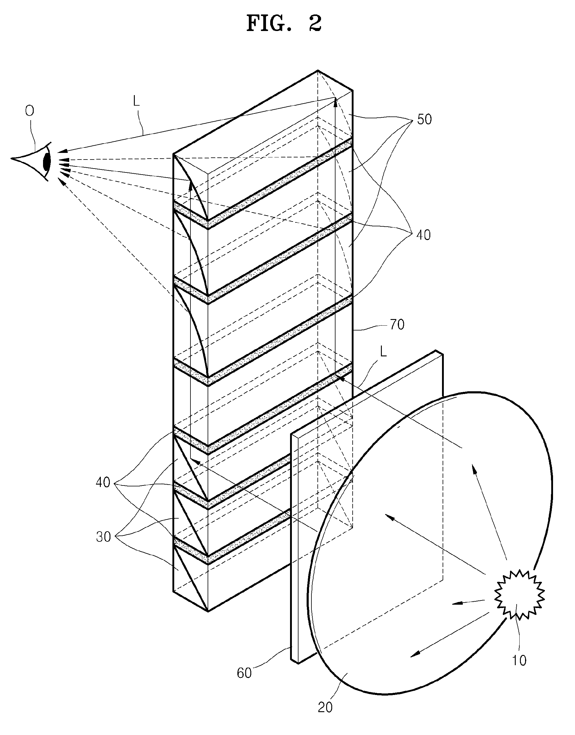
[0036]FIG. 2 is an illustration of a compact virtual display according to an embodiment of the present invention. FIG. 3 is a side cross-sectional view of the compact virtual display shown in FIG. 2.

[0037]Referring to FIGS. 2 and 3, the compact virtual display includes a light source 10, an illumination lens 20, an image receiving optical system 30, a polarization converting system 40, an image transmitting optical system 50, and an image display device 60.

[0038]The light source 10 may be a light emitting diode (LE...


PUM

PropertyMeasurementUnit
reflectionaaaaaaaaaa
transparentaaaaaaaaaa
refraction coefficientaaaaaaaaaa

Abstract

Provided is a compact virtual display in which an image displayed on an image display device is separated into a plurality of regions, selectively reflected in an image receiving optical system, and selectively transmitted in synchronization with the selective reflection of the image receiving optical system.

Description

CROSS-REFERENCE TO RELATED PATENT APPLICATION[0001]This application claims priority from Russian Patent Application No. 2008-125493, filed on Jun. 25, 2008, in the Russian Patent & Trademark Office, and Korean Patent Application No. 10-2009-0027758, filed on Mar. 31, 2009, in the Korean Intellectual Property Office, the disclosures of which are incorporated herein in their entirety by reference.BACKGROUND OF THE INVENTION[0002]1. Field of the Invention[0003]The present invention relates to an optical device, and more particularly to a device for receiving an optically magnified image, for example, a compact virtual display that can be located on a user's head or helmet.[0004]2. Description of the Related Art[0005]Compact virtual displays display images by using lenses, prisms, light pipes, electronic tubes, liquid crystal matrices, and the like. Compact virtual displays can be located on the users' heads to display images, and are then referred to as head-mounted displays (HMDs).[00...

Claims


Application Information

Patent Timeline
Patent Type & Authority Applications(United States)
IPC IPC(8): G09G5/00G02F1/03
CPCG02B5/30G02B17/006G02B17/086G02B27/017H04N9/3141G02B27/285G02B2027/014G09G2300/02H04N9/12G02B27/0172
Inventor PUTILIN, ANDREJ NIKOLAEVICHBRATISHEV, ALEKSEJ VLADIMIROVICH
Owner SAMSUNG ELECTRONICS CO LTD
Why Eureka
Try Eureka