
Conveying apparatus and printing apparatus

Inactive Publication Date: 2009-12-31
CANON KK
View PDF22 Cites 8 Cited by
  • Summary
  • Abstract
  • Description
  • Claims
  • Application Information

AI Technical Summary

Benefits of technology

[0007]The present invention has been made in view of the above disadvantage. It is an objective of the invention to further improve the conventional apparatus. A specific objective of the present invention is to allow an apparatus using a direct sensor to directly detect an object to thereby cope with an object moving with a higher speed (higher printing operation) than in the conventional case. A further objective of the present invention to allow the direct sensor to detect the moving information within a short time even when the processing section has a smaller computational power than in the conventional case.

Problems solved by technology

The direct sensor requires a huge amount of computation required for the image processing for the pattern matching.
This consequently causes a higher cost, causing an increasing cost for the printing apparatus.

Method used


Image

  • Conveying apparatus and printing apparatus
  • Conveying apparatus and printing apparatus
  • Conveying apparatus and printing apparatus

Examples


example 1

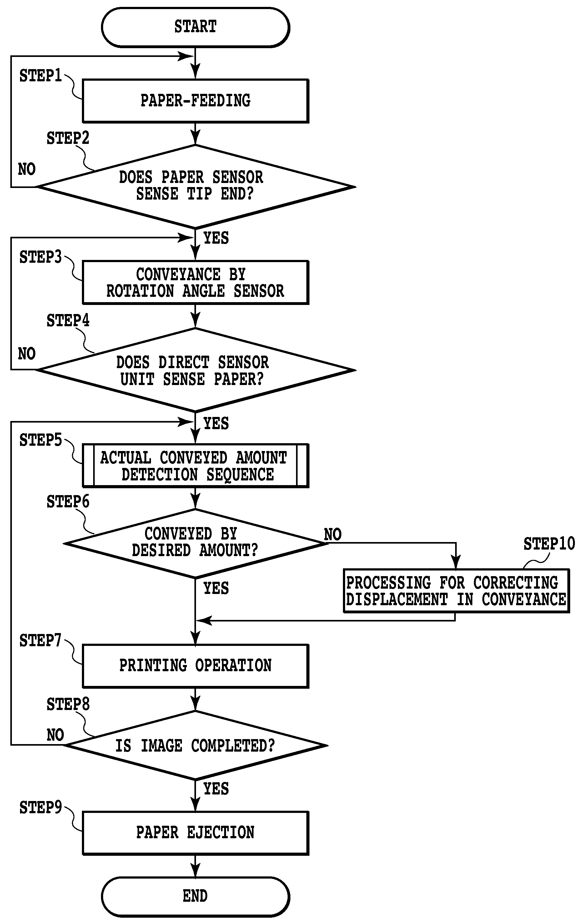
[0055]FIG. 10 is a flowchart illustrating the processing performed by a CPU 101 in the control of the conveyance of a print medium in this embodiment. FIG. 11 illustrates the conveyance status of a print medium in the respective steps shown in the flowchart.

[0056]When the printing operation is started based on a printing start command from the host apparatus 110, the CPU 101 drives the paper-feeding motor 35 to feed one print medium 8 from the auto sheet feeder 32 (STEP 1). Next, STEP 2 causes the CPU 101 to determine whether the paper sensor 33 senses the tip end of the print medium 8 or not. When determining that the tip end of the print medium 8 is detected, then the processing proceeds to STEP 3. When determining that the tip end of the print medium 8 is not yet detected in STEP 2 on the other hand, the processing returns to STEP 1 and continues the paper-feeding operation. Thereafter, until the tip end of the print medium is sensed, STEP 1 and STEP 2 are repeated. In FIG. 11, t...

example 2

[0080]Example 1 assumes a case where one target conveyed amount (one stepwise conveyance operation) is smaller than the detection region of the capturing element of the direct sensor unit 16 and one characteristic pattern (cross-shape pattern) is included in both of two pieces of image data acquired at different timings. In contrast with this, Example 2 is a control method for a case where one stepwisely-conveyed amount is larger than the length of arranged pixels of the direct sensor unit 16. The basic concept of this method is that a plurality of pieces of the image data are acquired in one stepwise moving to thereby perform the conveyance control.

[0081]The construction of the apparatus in Example 2 is the same as that in Example 1. The entire sequence is the same as that described in the flowchart of FIG. 10 except for that the method for the actual conveyance amount detection sequence in STEP 5 is different from that in Example 1. FIG. 17 is a flowchart illustrating the actual c...

example 3

[0094]Example 1 and Example 2 assume a case where one target conveyed amount is smaller or larger than the detection region of the direct sensor unit 16. On the other hand, Example 3 is a control method for a case where, even in the middle of one printing job, a set search range is within the range of the second image data or not within this range.

[0095]The apparatus in this example has the same configuration as that of Example 1. The entire sequence is the same as that described in the flowchart in FIG. 10 except for that the method of actual conveyance amount detection sequence in STEP 5 is different from that of Example 1. FIG. 20 is a flowchart illustrating the actual conveyance amount detection sequence in this example.

[0096]When the actual conveyance amount detection sequence is started, the CPU 101 in Step D01 firstly uses the direct sensor unit 16 to acquire the image of the print medium 8 as the first image data. When the direct sensor unit 16 is used to capture the surface...


PUM


Abstract

The apparatus comprising: a mechanism for moving an object; an information acquisition unit acquiring a driving amount information of the mechanism; a sensor for capturing a surface of the object; a processing section for processing a first image data and a second image data acquired by the sensor at different timings; and a control unit for controlling the mechanism, wherein: the processing section performs processings of: (a) cutting out an image pattern of a part of the first image data; (b) limiting a search range in the second image data within which a similar region similar to the image pattern is searched; (c) searching the similar region within the limited search range in the second image data; and (d) obtaining the moving information of the object based on a positional relation between the image pattern in the first image data and the similar region in the second image data.

Description

BACKGROUND OF THE INVENTION[0001]1. Field of the Invention[0002]The present invention relates to the technical field of sheet conveying preferably used in a printing apparatus.[0003]2. Description of the Related Art[0004]A printing apparatus has strict print quality-related requirements and now has a requirement for a further-improved accuracy. Thus, in order to detect the move of a sheet accurately to thereby realize a stable conveying by a feedback control, an attempt has been made to capture the surface of a sheet by an image sensor to detect the move of a conveyed sheet by an image processing.[0005]U.S. Pat. No. 7,104,710 discloses a method for detecting this move of a sheet. This method captures the surface image of a moving sheet by an image sensor a plurality of times to compare a plurality of resultant images by a pattern matching processing to detect a sheet moving distance based on the displacement amount the images. A sensor of the type according to which the sheet image ...

Claims


Application Information

Patent Timeline
IPC IPC(8): G06K15/02G06K9/00
CPCB41J11/42B41J11/0095H04N1/00015G06T7/20G03B17/00G01B11/25G01N21/956H04N7/0137G09G3/20G06F18/00
Inventor HAYASHI, MASASHIMORIYAMA, JIROTAKAHASHI, KIICHIROMURAYAMA, YOSHIAKIKONNO, YUJIYAZAWA, TAKESHI
Owner CANON KK
Features
  • Generate Ideas
  • Intellectual Property
  • Life Sciences
  • Materials
  • Tech Scout
  • Unparalleled Data Quality
  • Higher Quality Content
  • 60% Fewer Hallucinations
Learn More