Semiconductor memory device comprising a plurality of static memory cells
a memory device and static technology, applied in static storage, information storage, digital storage, etc., can solve the problems of difficult to compensate for the change of threshold voltage, complicated structure achieving the two kinds of power supplies, and become difficult to perform semiconductor memory devices. achieve the effect of simple circuit structure and stable writing and reading of data
- Summary
- Abstract
- Description
- Claims
- Application Information
AI Technical Summary
Benefits of technology
Problems solved by technology
Method used
Image
Examples
first embodiment
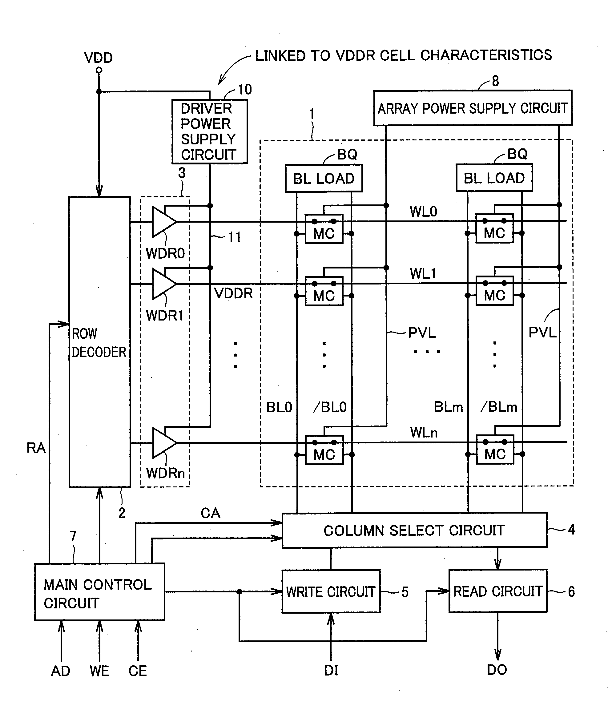
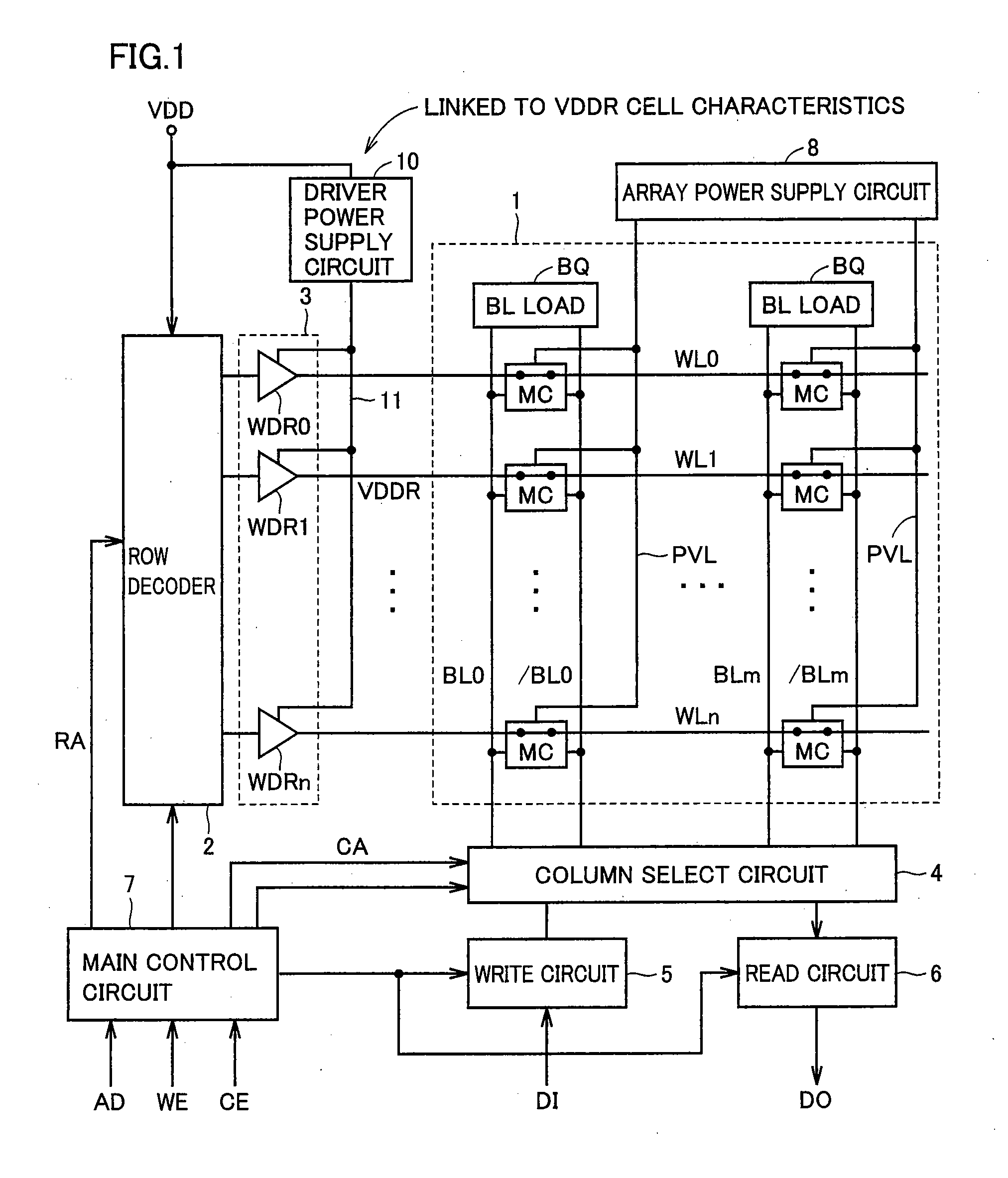
[0084]FIG. 5 schematically shows a major structure of the semiconductor memory device according to a first embodiment of the invention. In an example of memory cell array 1 shown in FIG. 5, memory cells MC are arranged in four rows and one column, and word lines WL0-WL3 are arranged corresponding to the respective rows. Word line drive circuit 3 includes word line drivers WDR0-WDR3 corresponding to word lines WL0-WL3, respectively. Driver power supply circuit 1 is provided with a series connection of a resistance element 20 and a pull-down element 21 shared among word line drivers WDR0-WDR3. For example, resistance element 20 employs an N+ polycrystalline silicon interconnection. Preferably, this resistance element is a non-silicide N+ polycrystalline silicon interconnection. Resistance element 20 that employs a passive element instead of a transistor can offer an advantage that a resistance value thereof does not change to a large extent even when a temperature changes. Pull-down e...
second embodiment
[0106]FIG. 9 shows a structure of driver power supply circuit 10 according to a second embodiment of the invention. In FIG. 9, driver power supply circuit 10 includes resistance element 20 connected between the power supply node and driver power supply line 11, and pull-down transistor 21 connected between driver power supply line 11 and a ground node. Resistance element 20 and pull-down transistor 21 have the same structures as those in the first embodiment. Therefore, pull-down transistor 21 is formed of the unit transistors (UTRs) of K in number connected in parallel.
[0107]Driver power supply circuit 10 further includes an N-channel MOS transistor 22 that is connected between the power supply node and an internal node 25, and has a gate connected to the power supply node, and an N-channel MOS transistor 24 that is connected between internal node 25 and the ground node, and has a gate, connected to internal node 25. These transistors 21, 22 and 24 form a pull-down circuit that low...
third embodiment
[0125]FIG. 12 schematically shows a structure of driver power supply circuit 10 according to a third embodiment of the invention. FIG. 12 likewise shows word line drivers WDR0-WDR3 in word line drive circuit 3, also shows memory cells MC arranged in four rows and one column in memory cell array 1 and word lines WL0-WL3 corresponding to the respective rows.
[0126]Driver power supply circuit 10 in FIG. 12 differs from driver power supply circuit 10 shown in FIG. 9 in the following structure. A resistance element 26 is used in stead of N-channel MOS transistor 24 formed of the logic transistor. Similarly to resistance element 20, resistance element 26 has an interconnection width equal to the gate length (channel length) of the N-channel MOS transistor in memory cell MC (see FIG. 8). Other structures of driver power supply circuit 10 shown in FIG. 12 are the same as those of the driver power supply circuit shown in FIG. 9. The corresponding portions bear the same reference numbers, and ...
PUM
 Abstract
Description
Claims
Application Information
 - R&D
- Intellectual Property
- Life Sciences
- Materials
- Tech Scout
- Unparalleled Data Quality
- Higher Quality Content
- 60% Fewer Hallucinations
Browse by: Latest US Patents, China's latest patents, Technical Efficacy Thesaurus, Application Domain, Technology Topic, Popular Technical Reports.
© 2025 PatSnap. All rights reserved.Legal|Privacy policy|Modern Slavery Act Transparency Statement|Sitemap|About US| Contact US: help@patsnap.com


