Expanded beam optical fibre connector

a technology of optical fibre connectors and expanded beams, applied in the field of optical connectors, can solve the problems of obscuring or degrading a portion of the expanded beam between the mated connector portions, difficult and time-consuming, damaged optical fibre cables, etc., and achieves the effect of ensuring alignment and reducing back-reflection between the optical fibre stub and the optical system

Inactive Publication Date: 2009-12-31
FIBERCO
View PDF2 Cites 66 Cited by
  • Summary
  • Abstract
  • Description
  • Claims
  • Application Information

AI Technical Summary

Benefits of technology

[0025]In a preferred embodiment of the invention, the ferrule is secured by means of a cured adhesive that extends between the ferrule and the optical system, in particular, said at least one lens. The adhesive is then preferably index matched and in contact with both the optical fibre stub and a surface of the optical system facing the fibre stub. In this way, back-reflections between the optical fibre stub and optical system can be minimised.
[0026]The cured adhesive may advantageously also extend over the first end of the ferrule, in order to make the alignment more secure.
[0027]It is particularly helpful if the cured adhesive overlaps the sleeve surrounding the ferrule to secure the sleeve axially with respect to the ferrule. This removes any need for additional components to secure the sleeve axially, and eliminates any need for the housing to provide this feature, or to have any close proximity to the sleeve.
[0028]In one embodiment of the invention, at least two vents, and preferably just a pair of vents, leading to the channel through the housing may extend from a location in the channel between the optical system and the second end of the ferrule. As will be described below, such vents are useful when introducing adhesive into the channel. To help prevent any contamination or moisture entering the channel during use of the connector, it is preferred if the cured adhesive blocks both vents.

Problems solved by technology

An optical fibre communications system may need to be used in a harsh environment where the connector may be subject to impacts, dirt or extremes of temperature and moisture.
Then, if dirt or moisture comes between the connector portions, this may only obscure or degrade a portion of the expanded beam between the mated connector portions.
Although such a connector is robust and economical, a problem arises if the optical fibre cable becomes damaged.
Although in principal it might be possible to separate the optical fibre from the connector, this would be difficult and time consuming.

Method used


Image

  • Expanded beam optical fibre connector
  • Expanded beam optical fibre connector
  • Expanded beam optical fibre connector

Examples


Embodiment Construction

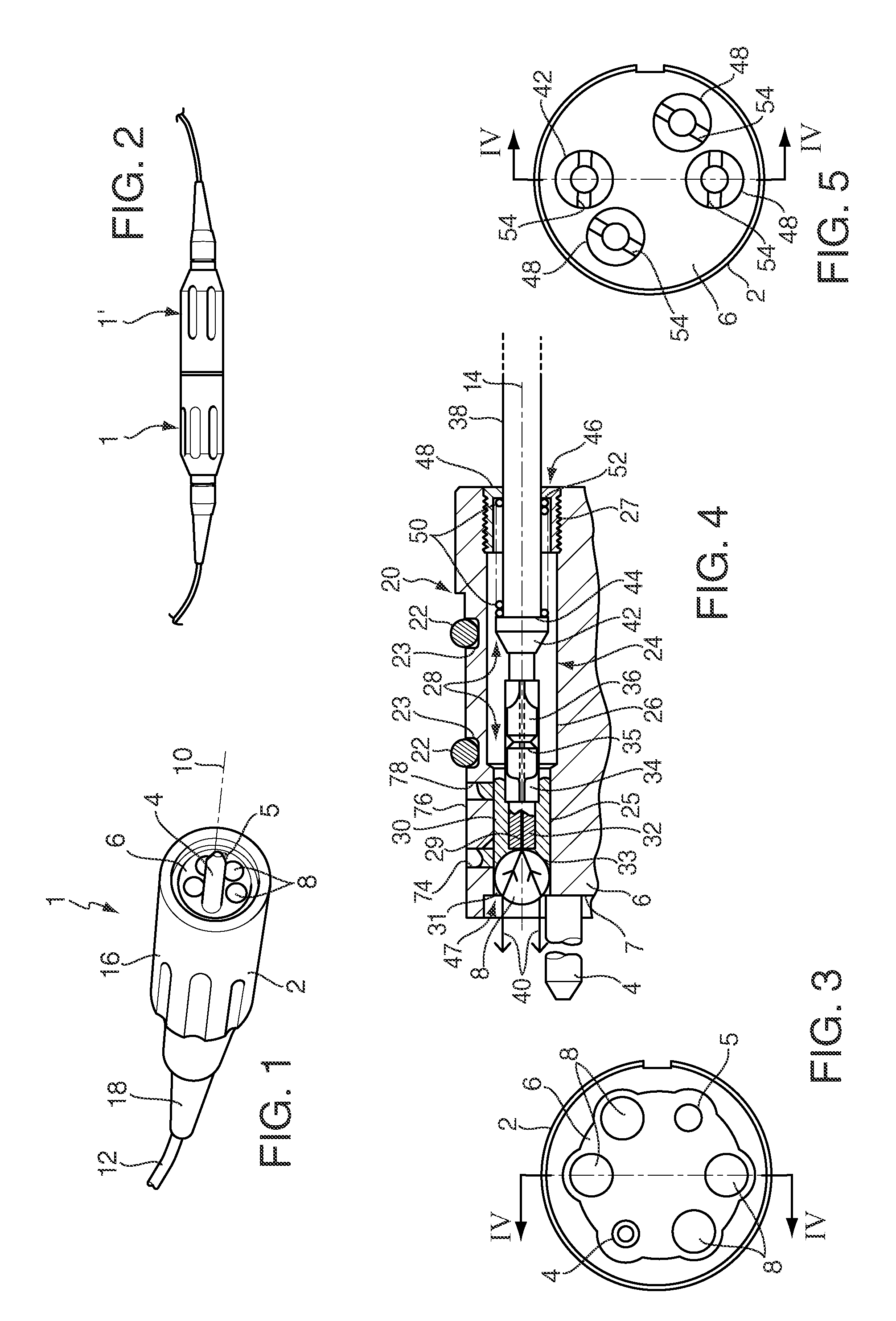
[0079]FIG. 1 shows a perspective view of an expanded beam connector assembly 1 having a generally cylindrical connector body portion or shell 2 with a hermaphroditic connection mechanism 4, 5 that surrounds a central fibre optic housing 6. The housing 6 holds four lenses 8, which here are spherical lenses, for four corresponding optical communication channels. The connector shell 2 defines a connector axis 10 which is in-line with a multi-fibre optic cable 12 that is terminated by the connector assembly 1, and parallel with an expanded beam connector axis 14, as shown in FIG. 4. The axis 14 is perpendicular to a front face 7 of the housing 6.

[0080]It should be noted however, that the number of lenses 8 and hence the number of communication channels is not critical to the invention, and that the connector assembly 1 may have any convenient number of lenses 8, for example between one and twelve lenses.

[0081]FIG. 2 shows how two such connector assemblies 1, 1′ may be joined together. A...


PUM

PropertyMeasurementUnit
diameteraaaaaaaaaa
diameteraaaaaaaaaa
lengthaaaaaaaaaa

Abstract

The present invention relates to an optical connector for use in a fibre optic communications system, and particularly an expanded beam optical connector (20) for connecting optical fibres. The connector (20) comprises a housing (6), a port (48) within the housing for receiving an end (35) of an optical fibre (38), a cylindrical ferrule (32) within the housing (6) having opposite first and second ends (33, 35), and an optical fibre stub held axially (14) within the ferrule (32) and extending between said ferrule ends (33, 35). The connector (20) also has a lens (8) for projecting and/or receiving an expanded beam (40) optically coupled with the optical fibre stub at the first ferrule end (33). A sleeve (34) surrounds the ferrule (32) and extends towards the port (48) axially away from the second ferrule end (35) to present an open end to the sleeve for receiving a termination ferrule (36) of an optical fibre (38) inserted into the port. The connector (20) has a connector portion (2, 4, 5) for connecting the optical fibre connector (20) to another expanded beam optical fibre connector so that said expanded beam (40) traverses between the connectors. A channel (28) extends through the housing (6) from the port (48) towards the lens (8), the ferrule (32) being secured by means of a cured adhesive (30) to the housing (6) and in alignment with respect to the lens (8), the open end of the sleeve (34) and/or the second end (35) of the ferrule being surrounded by a void (60) within the channel (28).

Description

BACKGROUND[0001]a. Field of the Invention[0002]The present invention relates to an optical connector for use in a fibre optic communications system, and particularly an expanded beam optical connector for connecting optical fibres.[0003]b. Related Art[0004]An optical fibre communications system may need to be used in a harsh environment where the connector may be subject to impacts, dirt or extremes of temperature and moisture. One application where optical connectors are used in a harsh environment is in the broadcast industry, where cameras or sound equipment are joined to other electronic equipment by means of fibre optic cables extending across open spaces. The cables may be joined together with optical connectors that may have to lie on the open ground where dirt or mud may find their way into the connector.[0005]One known way to increase the reliability of an optical connector is to make use of an expanded collimated optical beam which is projected between mating connector por...

Claims


Application Information

Patent Timeline
Patent Type & Authority Applications(United States)
IPC IPC(8): G02B6/38B23P11/00G02B6/36
CPCG02B6/32G02B6/3816G02B6/383G02B6/3846Y10T29/49826G02B6/3877G02B6/3878G02B6/3882G02B6/3867
Inventor EVERETT, DAVID EDWARDCURRAN, DOMINIC PATRICK DANIEL
Owner FIBERCO
Why Eureka
Try Eureka