Insulator for stator assembly of brushless DC motor

a stator assembly and electric motor technology, applied in the field of electric motors, can solve the problems of increasing cost and complexity in the manufacturing process, no mechanical purpose, and conventional approaches to the foregoing are not optimal solutions, and achieve the effect of increasing mechanical integrity

Active Publication Date: 2009-12-31
RESMED MOTOR TECH
View PDF13 Cites 155 Cited by
  • Summary
  • Abstract
  • Description
  • Claims
  • Application Information

AI Technical Summary

Benefits of technology

[0011]Another aspect of the present invention relates to an insulator for a stator assembly including a stator core having a plurality of teeth, coils wound around the teeth, and a PCBA. The insulator includes at least one insulator adapted to be mounted to the stator core and structured to insulate the stator core from the coils. The at least one insulator includes structure or features to perform at least one additional function. For example, the structure or features may include features to support and / or locate the PCBA on the stator core, guide features that guide cross-over wires that form a connection between coils, and / or positioning features to precisely position the PCBA and its attendant components accurately with respect to the coils.
[0020]Other aspects of the invention relate to an insulator integrally molded with the stator core with the same functionality for mounting a PCBA that interacts via a magnetic field with the optionally laminated rotor, cylindrical magnet optionally overhanging the rotor hub and provided with Hall sensors, thermal sensors, etc., wire routing thru-slot for packaging and strain relief (to insulate and help protect the solder joint from strain), “plate through” feature at edge of PCB, and / or steel sleeve on outer diameter of rotor magnet (for increased mechanical integrity).

Problems solved by technology

However, achieving each of these functions separately drives up cost and complexity in the manufacturing process.
Conventional approaches to the foregoing are not optimal solutions when a PCBA is to be accurately positioned on the stator.
Each of these is useful as an insulator, however, there is no mechanical purpose served, i.e., they are only insulators.
While these approaches all function for the intended purpose, they may not be optimal in terms of cost and compactness.

Method used


Image

  • Insulator for stator assembly of brushless DC motor
  • Insulator for stator assembly of brushless DC motor
  • Insulator for stator assembly of brushless DC motor

Examples


Embodiment Construction

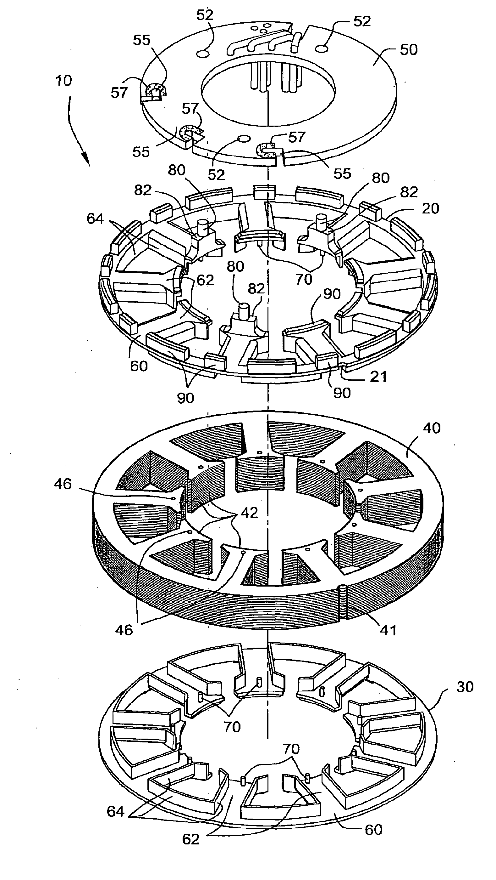
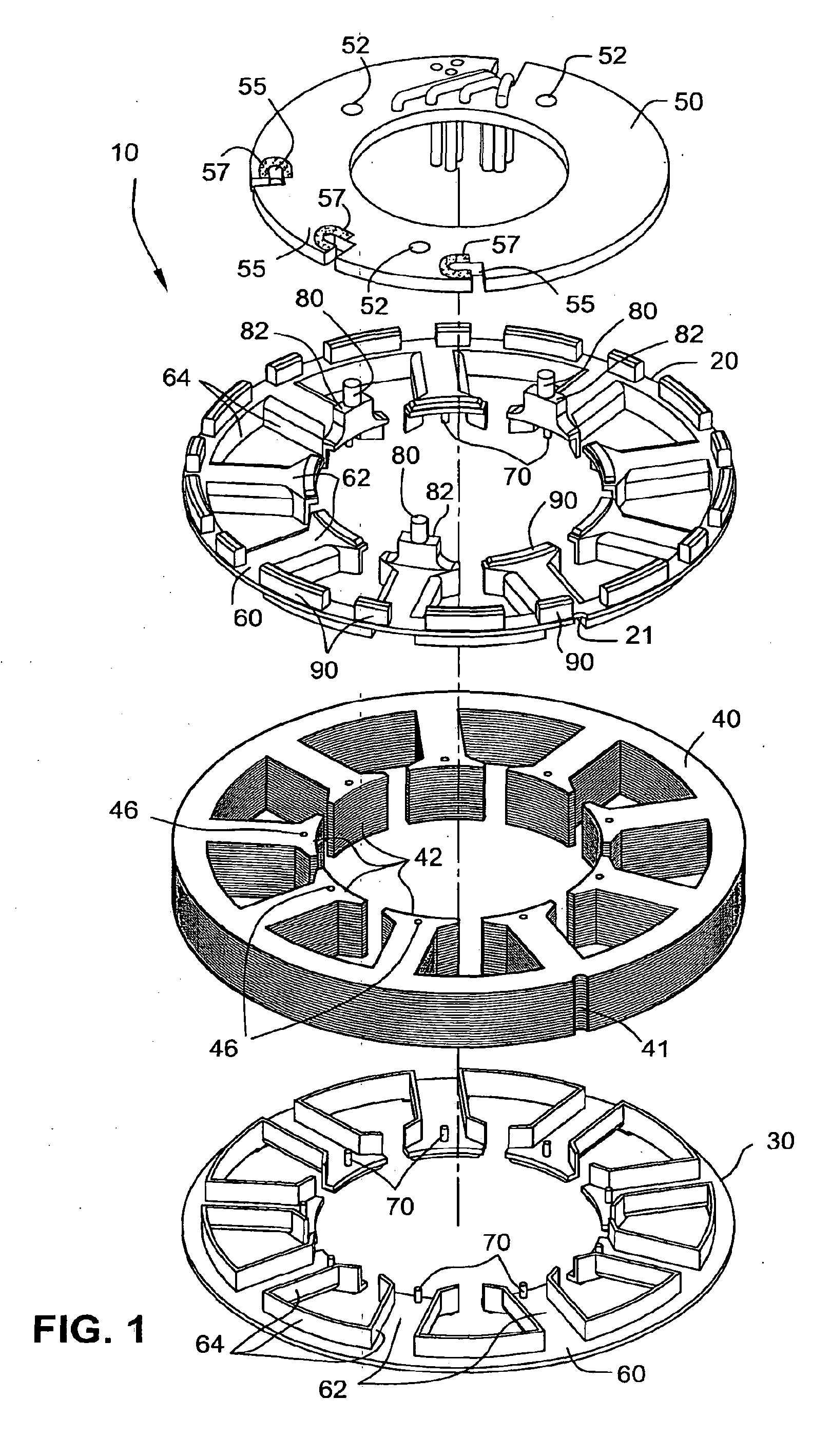
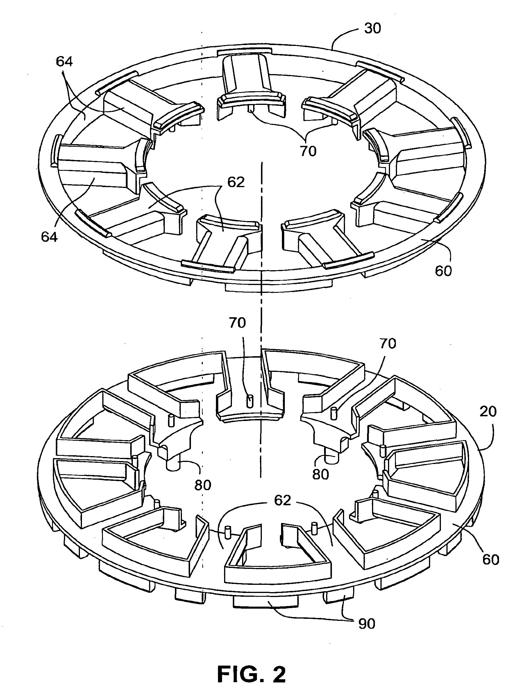
[0042]FIGS. 1-9 illustrate a stator assembly 10 including an insulator having first and second insulators 20, 30 according to an embodiment of the present invention. In the illustrated embodiment, the stator assembly 10 is implemented into an electric motor in the form of a brushless DC motor (see FIG. 11).

[0043]As best shown in FIG. 11, the stator assembly 10 is adapted to surround a rotor 11 having a shaft 12 and a magnet 13 having a plurality of magnetic poles. In an embodiment, a steel sleeve may be provided to an outer diameter of the magnet for increased mechanical integrity. One or both end portions of shaft 12 are adapted to be coupled to or provided with a respective impeller 14 to pressurize gas received from an intake. In use, an electronic controller (typically provided as part of PAP devices or flow generators available from ResMed) controls operation of the motor to control spinning movement of the rotor 11 and hence the load, e.g., impeller 14.

1.0 Insulators

[0044]As b...


PUM

PropertyMeasurementUnit
angleaaaaaaaaaa
angleaaaaaaaaaa
internal diameteraaaaaaaaaa

Abstract

An insulator for a stator assembly includes at least a first insulator adapted to be mounted to the stator core and structured to insulate the stator core from the coils. The at least one insulator includes structure to perform at least one additional function. For example, the structure may include a support member to support and / or locate the PCBA on the stator core, a wire guide to guide cross-over wires that form a connection between coils, and / or positioning structure to precisely position the PCBA with respect to the coils.

Description

CROSS-REFERENCE TO APPLICATIONS[0001]This application claims the benefit of U.S. Provisional Application Nos. 60 / 841,564, filed Sep. 1, 2006, and 60 / 929,867, filed Jul. 16, 2007, each of which is incorporated herein by reference in its entirety.[0002]Also, U.S. Provisional Application Nos. 60 / 730,875, filed Oct. 28, 2005, and 60 / 775,333, filed Feb. 22, 2006, are each incorporated herein by reference in its entirety.FIELD OF THE INVENTION[0003]The present invention relates to electric motors, and more particularly to an insulator for a stator assembly of an electric motor. The present invention also relates to electric blowers, e.g., positive airway pressure (PAP) devices or flow generators used for treatment of Sleep Disordered Breathing (SDB) with Non-Invasive Positive Pressure Ventilation (NIPPV). Of course, the teachings herein also have general application to electric motors in virtually any technical application.BACKGROUND OF THE INVENTION[0004]A need has developed in the art f...

Claims


Application Information

Patent Timeline
Patent Type & Authority Applications(United States)
IPC IPC(8): F04D25/08H02K3/34H02K15/085
CPCY10T29/49316H02K3/522H02K7/14Y10T29/49009H02K2203/03H02K2203/09H02K2203/12
Inventor SEARS, DAVID B.MOIR, MICHAEL BRUCETHOMAS, PETER JEFFREY
Owner RESMED MOTOR TECH
Why Eureka
Try Eureka