
Methods and apparatus for in-situ chamber dry clean during photomask plasma etching

a plasma etching and in-situ chamber technology, applied in the direction of originals for photomechanical treatment, instruments, fluid pressure measurement, etc., can solve the problems of inability to achieve dry cleaning in-situ, reduced mask production, and inability to repair photomask defects,

Inactive Publication Date: 2009-12-31
APPLIED MATERIALS INC
View PDF4 Cites 20 Cited by
  • Summary
  • Abstract
  • Description
  • Claims
  • Application Information

AI Technical Summary

Problems solved by technology

When the deposited etch by-products reach a certain thickness, the by-products may peel off the inner wall and contaminate the photomask by falling onto the substrate, causing irreparable defects to the photomask.
However, such a wet cleaning approach is time-consuming, resulting in the disadvantage of reduced mask production.
In-situ dry cleaning has also been utilized in other plasma chambers, but commercially viable in-situ dry cleaning processes suitable for photomask etch processes are not known.

Method used


Image

  • Methods and apparatus for in-situ chamber dry clean during photomask plasma etching
  • Methods and apparatus for in-situ chamber dry clean during photomask plasma etching
  • Methods and apparatus for in-situ chamber dry clean during photomask plasma etching

Examples


Embodiment Construction

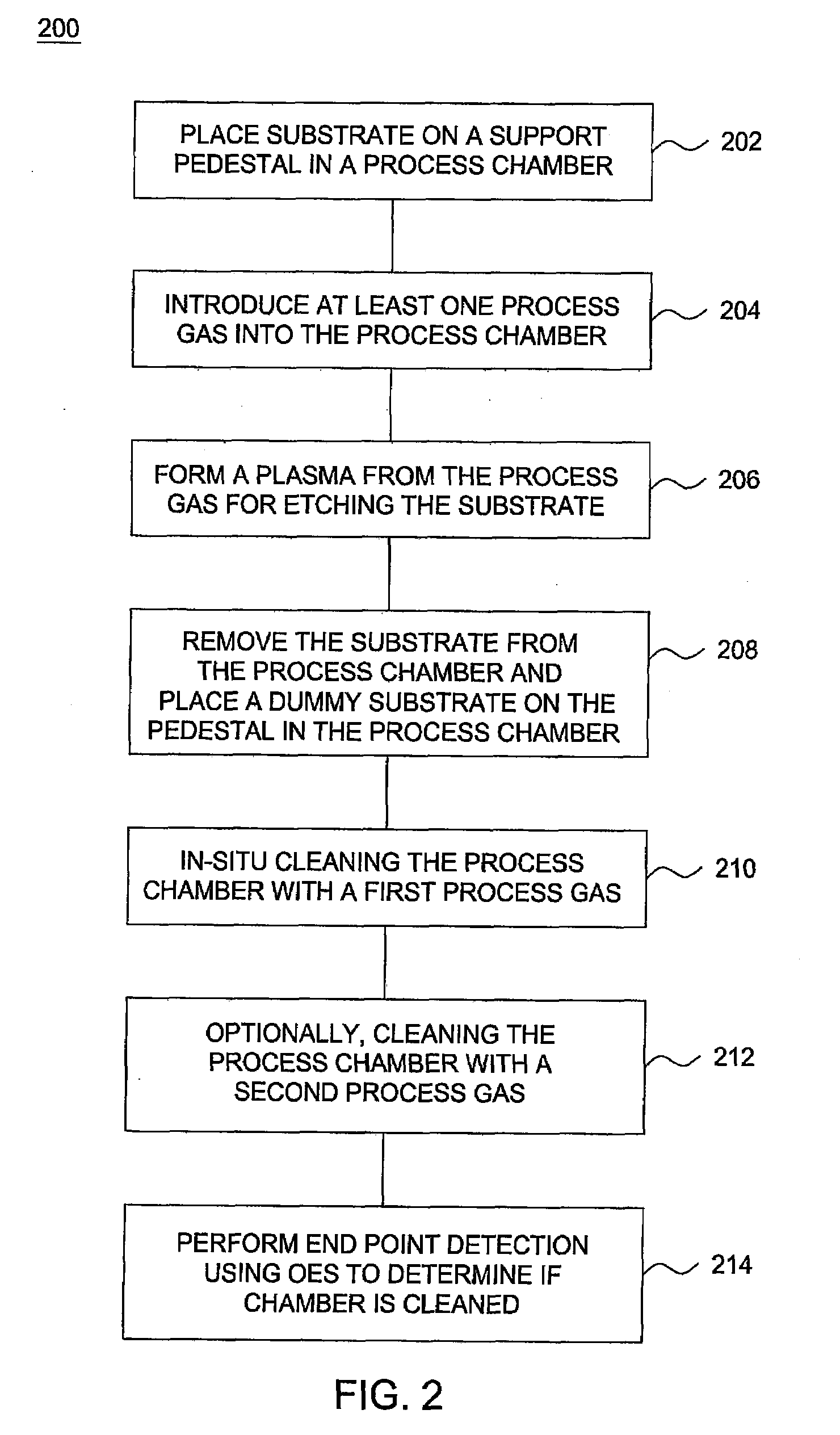
[0017]Embodiments of the present invention provide methods and apparatus for in-situ chamber dry clean during photomask plasma etching.

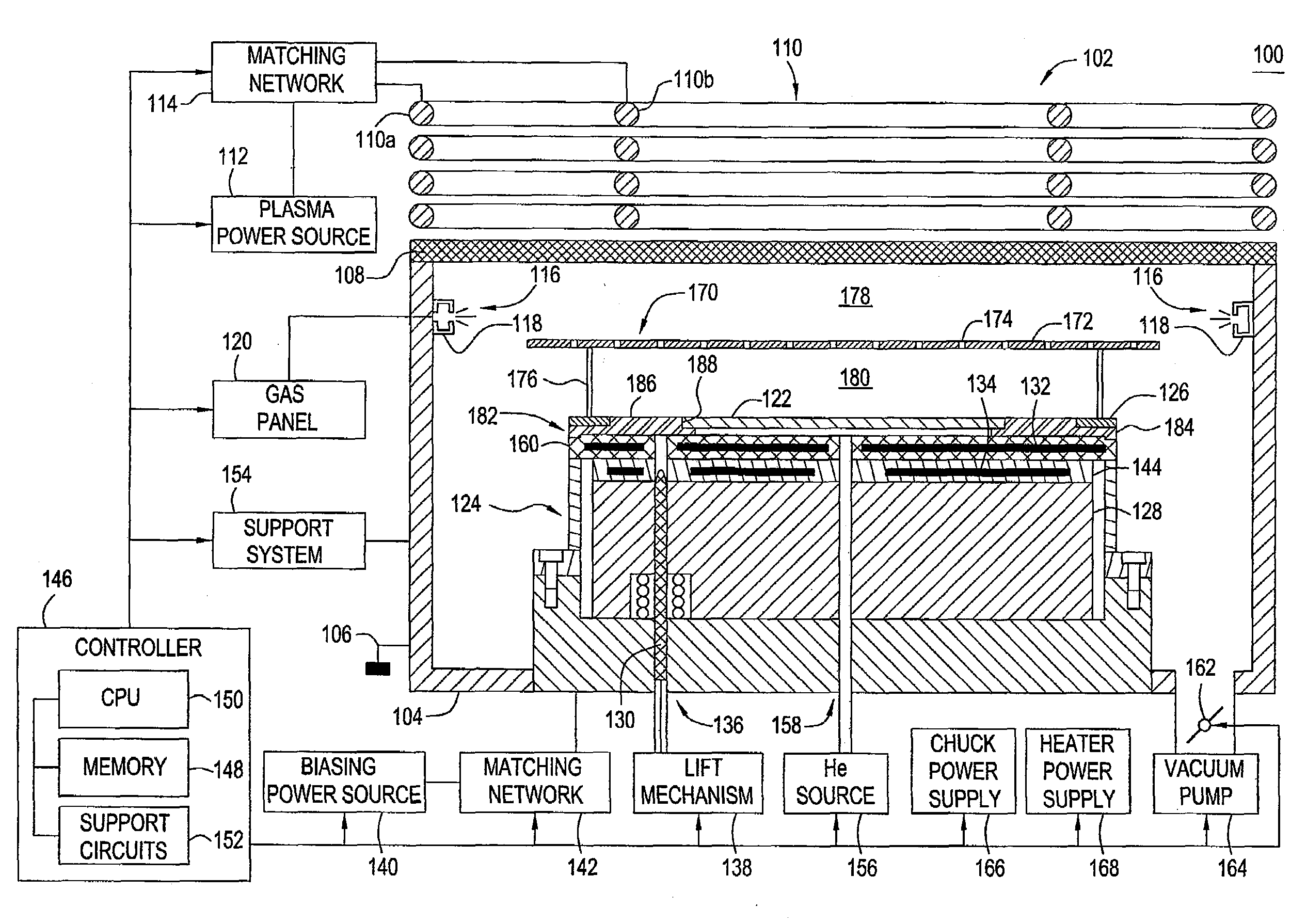
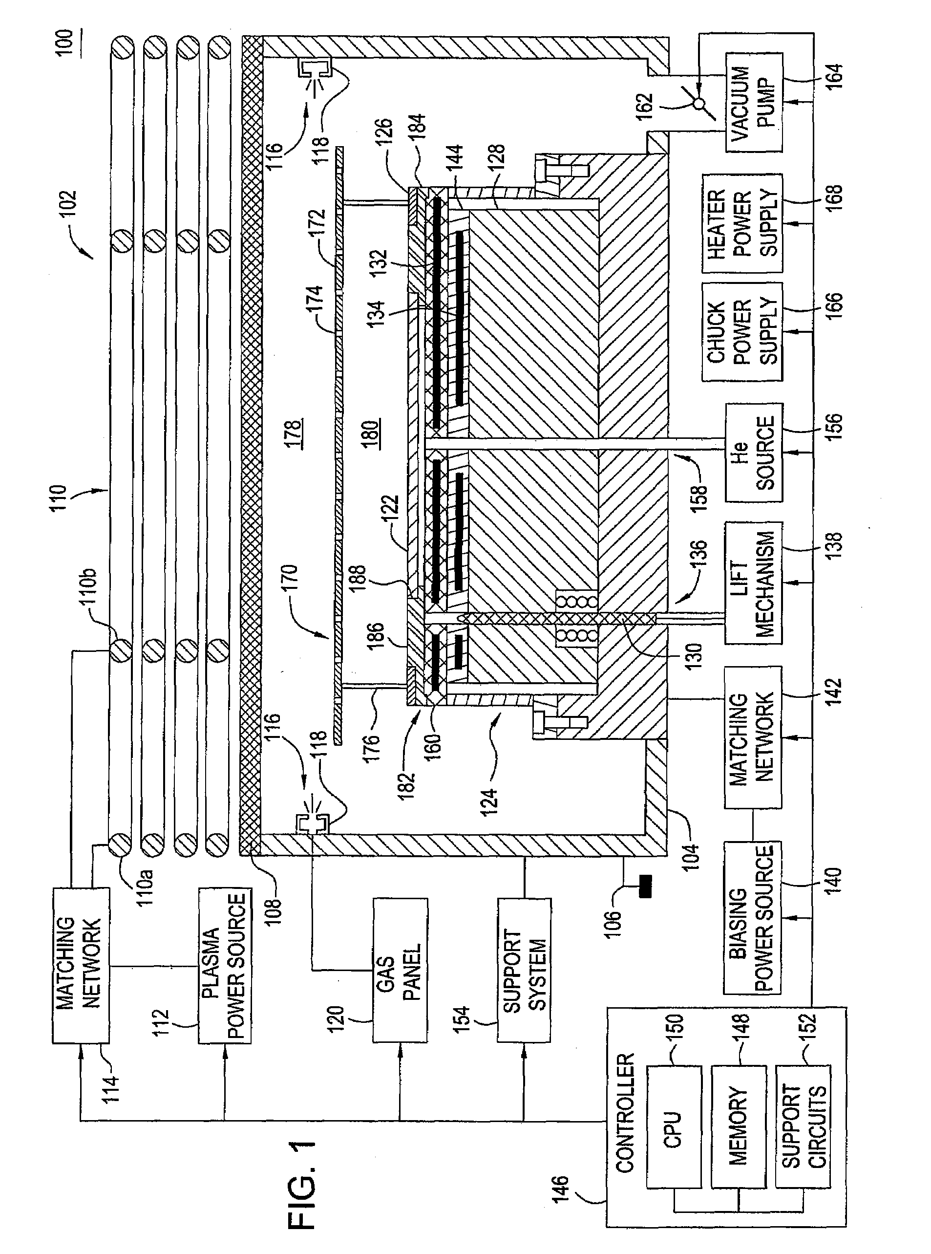
[0018]FIG. 1 depicts a schematic diagram of an etch reactor 100 in which the invention may be practiced. Suitable reactors that may be adapted for use with the teachings disclosed herein include, for example, a Decoupled Plasma Source (DPS® II) reactor, or a TETRA® Photomask etch system, all of which are available from Applied Materials, Inc. of Santa Clara, Calif. The particular embodiment of the reactor 100 shown herein is provided for illustrative purposes and should not be used to limit the scope of the invention. It is contemplated that the invention may be utilized in other plasma processing chambers, including those from other manufacturers.

[0019]The reactor 100 generally comprises a process chamber 102 having a substrate pedestal 124 within a conductive body (wall) 104, and a controller 146. The process chamber 102 has a substantially flat di...


PUM

PropertyMeasurementUnit
internal pressureaaaaaaaaaa
frequencyaaaaaaaaaa
frequencyaaaaaaaaaa

Abstract

Embodiments of the invention include method for in-situ chamber dry clean after photomask plasma etching. In one embodiment, the method includes placing a photomask upon a support pedestal, introducing a process gas into a process chamber, forming a plasma from the process gas, etching a chromium containing layer disposed on the photomask in the presence of the plasma, removing the photomask from the support pedestal, placing a dummy substrate on the pedestal and performing an in-situ dry cleaning process by flowing a cleaning gas containing O2 through the process chamber while the dummy substrate is disposed on the support pedestal.

Description

BACKGROUND[0001]1. Field[0002]Embodiments of the present invention generally relate to method and apparatus for processing a photomask substrate using plasma etching. Particularly, embodiments of the present invention relate to methods and apparatus for in-situ chamber dry clean during plasma etching of photomask substrates.[0003]2. Description of the Related Art[0004]The fabrication of microelectronics or integrated circuit devices typically involves a complicated process sequence requiring hundreds of individual steps performed on semiconductive, dielectric and conductive substrates. Examples of these process steps include oxidation, diffusion, ion implantation, thin film deposition, cleaning, etching and lithography. Using lithography and etching (often referred to as pattern transfer steps), a desired pattern is first transferred to a photosensitive material layer, e.g., a photoresist, and then to the underlying material layer during subsequent etching. In the lithographic step,...

Claims


Application Information

Patent Timeline
Patent Type & Authority Applications(United States)
IPC IPC(8): H01L21/3065B44C1/22
CPCH01J37/32862G03F1/80H01L21/0274H01L21/3065
Inventor CHEN, XIAOYIMAO, ZHIGANGKNICK, DAVIDGRIMBERGEN, MICHAELBIVENS, DARINCHANDRAHOOD, MADHAVIIBRAHIM, IBRAHIMKUMAR, AJAY
Owner APPLIED MATERIALS INC
Learn More