Trailer Refrigeration System

a refrigeration system and trailer technology, applied in the field of refrigeration systems, can solve the problems of cumbersome and complicated maintenance work poor maintainability of the sub engine, etc., and achieve the effects of enhancing the maintainability of the electricity-generator engine, enhancing the flexibility of the installation location, and facilitating removal

Inactive Publication Date: 2010-01-07
DAIKIN IND LTD
View PDF7 Cites 22 Cited by
  • Summary
  • Abstract
  • Description
  • Claims
  • Application Information

AI Technical Summary

Benefits of technology

[0017]Therefore, in accordance with the present invention, the electricity generator (22) and the electricity-generator engine (21) are contained in one unit while on the other hand the electric compressor (31) is contained in another unit, and the units (U1, U2) are electrically connected together and as a result it is possible to easily remove only the unit (U1) containing the electricity generator (22) and the electricity-generator engine (21) from the vehicle. This enhances the maintainability of the electricity-generator engine (21) et cetera.
[0018]In addition, since the units (U1, U2) are electrically connected together, each unit is freed from the constraint imposed by the other unit. That is, it is possible to enhance the flexibility of the location of installation of each unit (U1, U2). Accordingly, if the units (U1, U2) are arranged such that they are spaced apart as much as possible, the refrigerant circuit in which the electric compressor (31) is disposed is not subjected to the influence of heat generated by the electricity-generator engine (21) et cetera. This therefore accomplishes the energy saving of the refrigeration operation.
[0019]In addition, in accordance with the second aspect of the present invention, the converter (23) and the inverter (24, 25, 26) are connected to between the electricity generator (22) and the electric compressor (31), thereby making it possible to individually control the speed of rotation of the electricity-generator engine (21) and the speed of rotation of the electric compressor (31). Accordingly, there is no need that, being constrained by the al...

Problems solved by technology

This especially produces the problem of poor maintainability of the sub engine.
Besides, the work of maintenance of the sub engine is cumbersome and compli...

Method used


Image

  • Trailer Refrigeration System
  • Trailer Refrigeration System
  • Trailer Refrigeration System

Examples


Embodiment Construction

[0039]Referring to the drawings, an embodiment of the present invention is described in detail below.

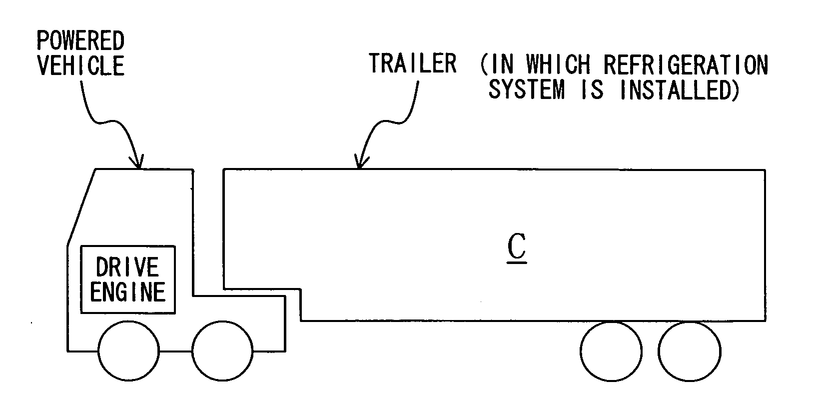
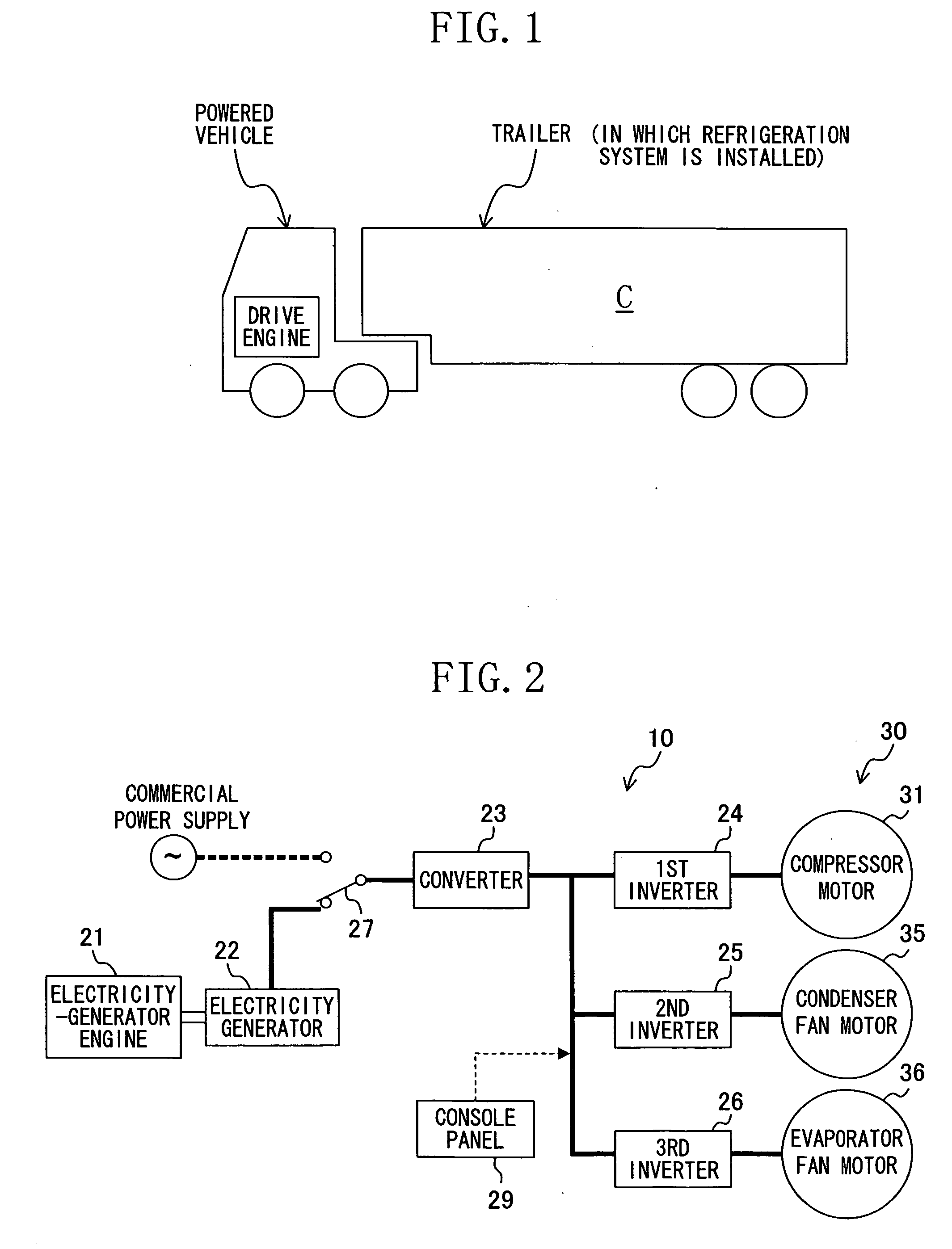
[0040]Referring to FIG. 1, there is shown a large refrigeration vehicle used for ground transportation of frozen foods, fresh foods et cetera, and a refrigeration system (10) of the present embodiment is incorporated into the refrigeration vehicle. The refrigeration vehicle includes a powered vehicle (trailer head) having a driver's cabin and a drive engine, and a cargo-carrying platform vehicle (trailer) having a refrigeration storage compartment (C). The trailer head and the trailer are detachably connected together. The refrigeration system (10) of the present embodiment is installed in the cargo-carrying platform vehicle (trailer) and provides cooling of the inside of the refrigeration storage compartment (C).

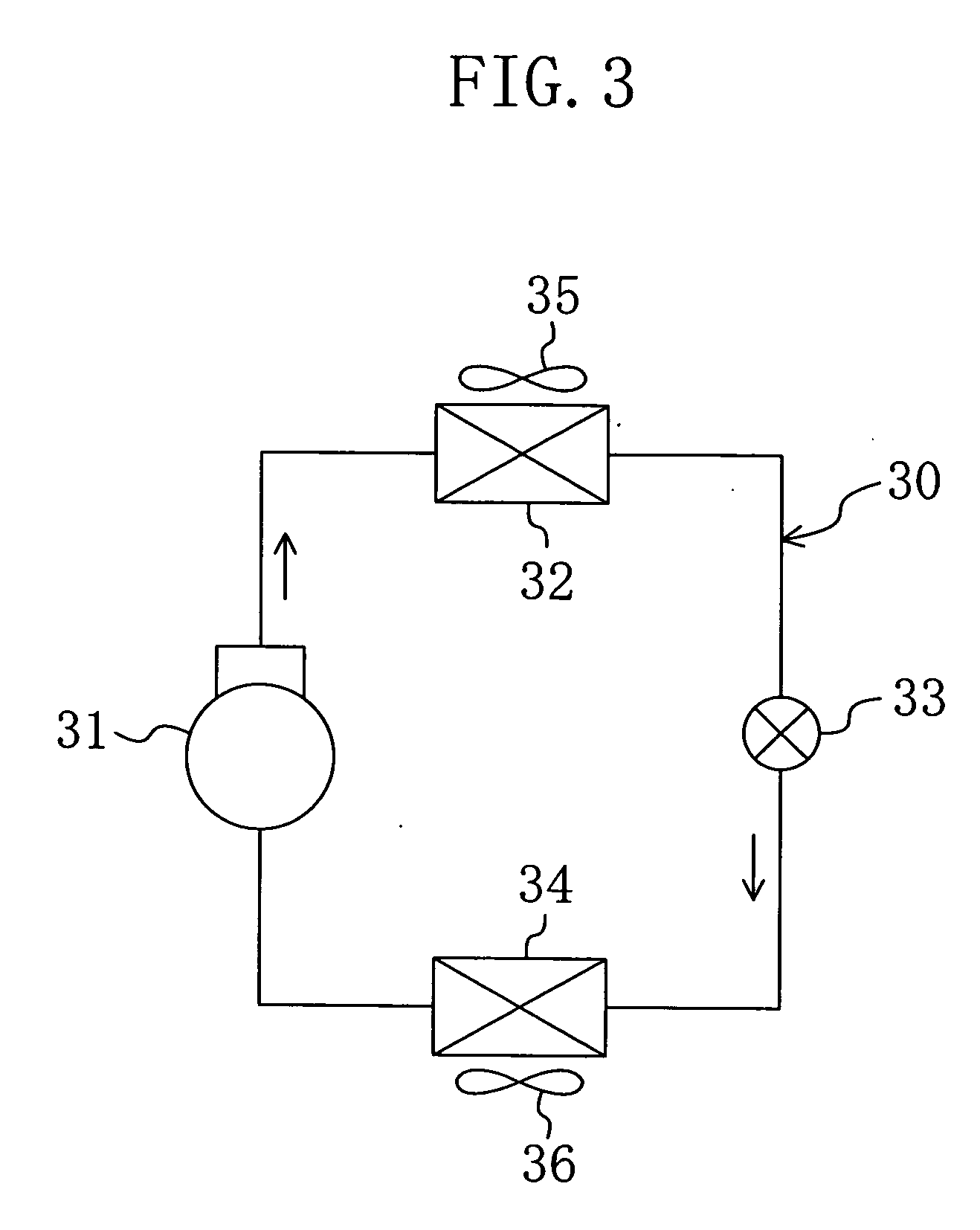
[0041]As shown in FIGS. 2 and 3, the refrigeration system (10) includes an electricity-generator engine (21), an electricity generator (22), a converter (23), three inverter...


PUM


Abstract

An engine unit (U1) containing an electricity generator (22), an electricity-generator engine (21), and a console panel (29) is mounted in the lower part of a trailer. A refrigeration equipment unit (U2) containing a converter (23), inverters (24, 25, 26), and a refrigerant circuit (30) is mounted in the ceiling part of a refrigeration storage compartment (C). The engine unit (U1) and the refrigeration equipment unit (U2) are connected together by electric wiring.

Description

TECHNICAL FIELD[0001]In general, the present invention relates to a refrigeration system intended for use in a transport trailer. More specifically, the present invention relates to a technology for enhancing the maintainability of the trailer refrigeration system.BACKGROUND ART[0002]In the past, refrigeration systems, which are installed in refrigeration vehicles for ground transportation of frozen foods et cetera and used to provide cooling of the inside of their freezing storage compartments, have been known in the art (see, for example, Japanese Patent Document JP-A-H05(1993)-38933). Such a refrigeration system includes a sub engine separate from the drive engine of the refrigeration vehicle and an electric compressor driven by the sub engine, and is installed in the cargo-carrying platform.DISCLOSURE OF THE INVENTION[0003]Problems that the Invention Seeks to Overcome[0004]However, in the refrigeration system of the patent document, the sub engine and the compressor motor are in...

Claims


Application Information

Patent Timeline
IPC IPC(8): B60H1/32
CPCB60H1/00014B60H1/00428B60H1/3226F25D29/003F25B27/00F25B2600/021B60P3/20Y02T10/88
Inventor KITANO, SHIGEICHIYAKUSHIJI, FUMIAKINISHIHAMA, YUKIOKUDOU, KEISUKEMIZUTANI, YASUTOSHI
Owner DAIKIN IND LTD
Why Eureka
Try Eureka