Solar-assisted climate control system

a technology of solar energy and climate control, which is applied in the direction of domestic cooling equipment, lighting and heating equipment, heating types, etc., can solve the problems of high air conditioning load, low energy efficiency, and low sensible air conditioning load

Inactive Publication Date: 2010-01-07
DELPHI TECH INC
View PDF4 Cites 60 Cited by
  • Summary
  • Abstract
  • Description
  • Claims
  • Application Information

AI Technical Summary

Benefits of technology

[0013]In summary, the invention is a method for providing climate control. The method includes the step of circulating liquid desiccant in a first fluid circuit. The method also includes the step of disposing a dehumidifier along the first fluid circuit. The method also includes the step of disposing a regenerator along the first fluid circuit downstream of the dehumidifier. The method also includes the step of harnessing solar energy with at least one solar collector. The method also includes the step of circulating coolant in a second fluid circuit. At least one solar collector and the regenerator are both disposed along the second fluid circuit whereby the coolant is heated during passage adjacent to the solar collector and transfers thermal energy to the liquid desiccant during passage through the regenerator. The first and second fluid circuits are in parallel in the regenerator.

Problems solved by technology

However, it is not very energy efficient due to the fact that the mechanical compressor used in the vapor compression system requires a large amount of energy.
Whereas a decrease in the dry bulb temperature is the desired effect resulting in lower sensible air conditioning load, increase in the absolute humidity is the undesired effect resulting in higher air conditioning load.
Thus direct evaporative cooling is counterproductive to some extent.

Method used


Image

  • Solar-assisted climate control system
  • Solar-assisted climate control system
  • Solar-assisted climate control system

Examples


Embodiment Construction

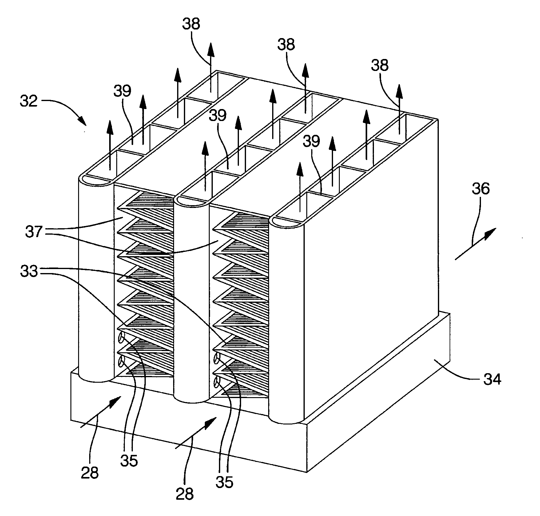
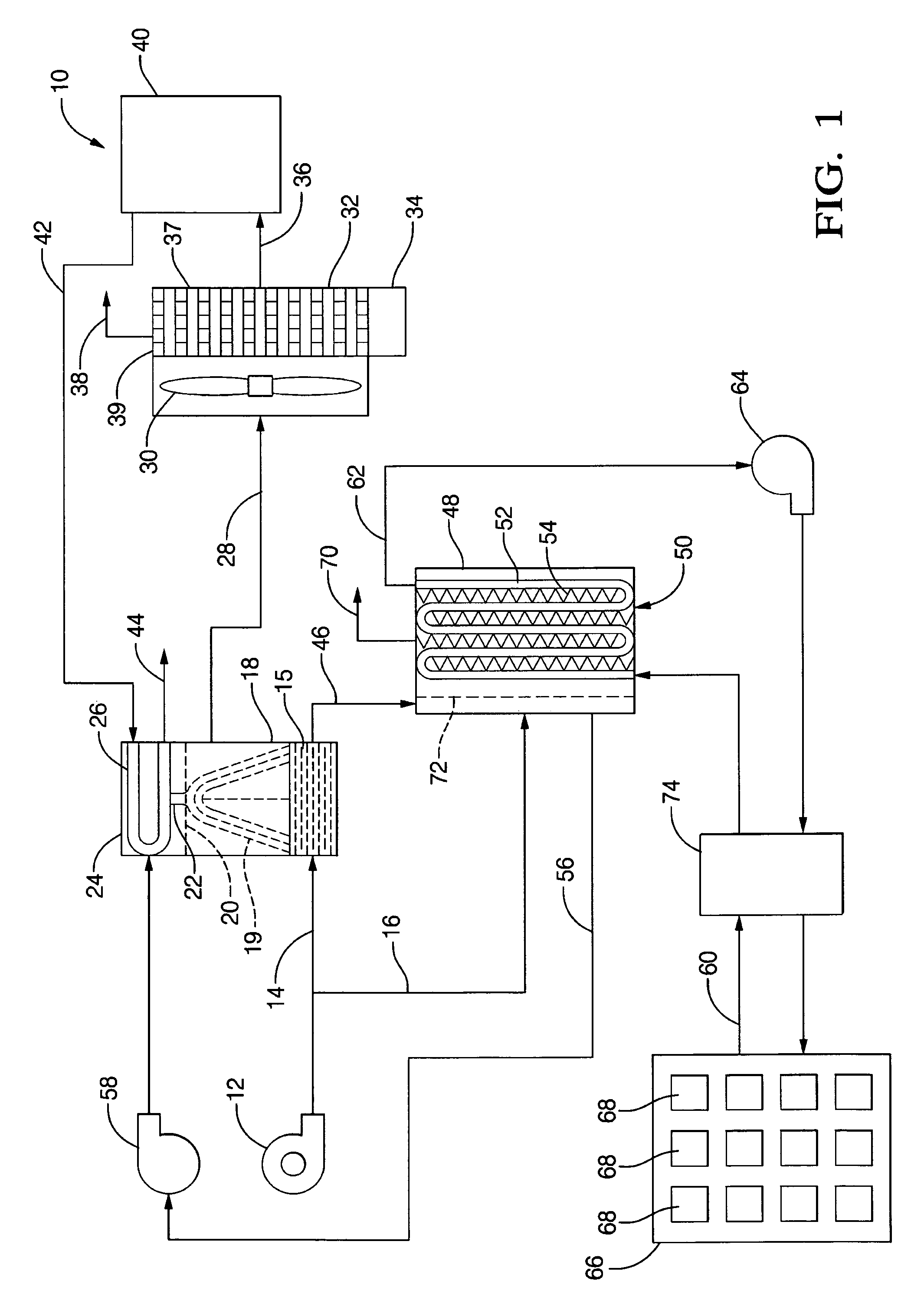
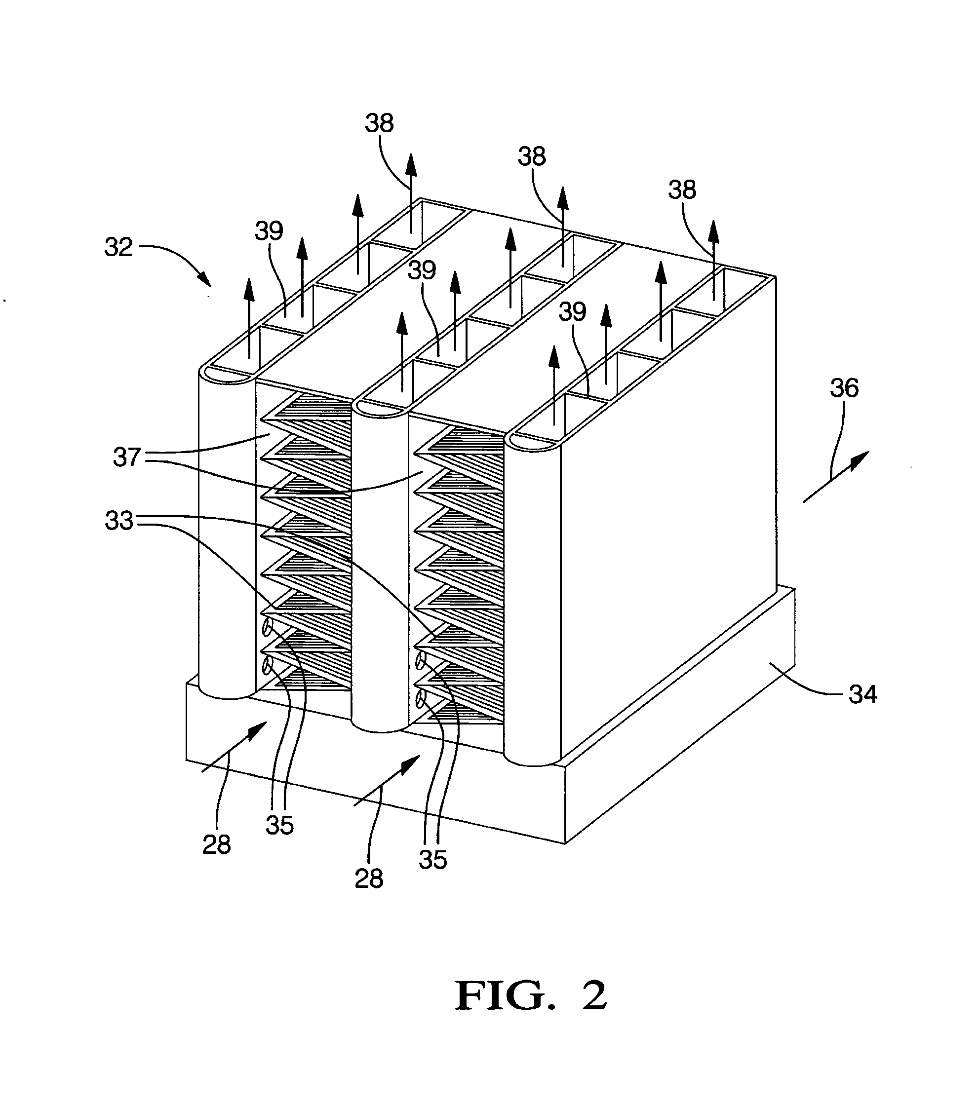
[0018]In the exemplary embodiment of the present invention, a dehumidifier with a liquid desiccant is employed to handle the latent load of the air conditioning system. The liquid dehumidifier operates in conjunction with a regenerator which reconstitute the dilute desiccant by removing moisture therefrom thereby ensuring continuous operation of the air conditioning system.

[0019]The solar-powered comfort heating and cooling system comprises an indirect evaporative cooler operating in series with an air dehumidifier. The function of the indirect evaporative cooler is to handle the sensible load and that of the dehumidifier is to handle the latent load of the system. The liquid desiccant used in the air dehumidifier is reconstituted in a shell-and-tube type of regenerator using a coolant heated by an array of solar collectors. An auxiliary heater operating in series with the solar collector array is provided to heat the coolant when there is no sunshine or when the solar heating needs...


PUM


Abstract

A method for providing climate control is disclosed herein. The method includes the step of circulating liquid desiccant in a first fluid circuit. The method also includes the step of disposing a dehumidifier along the first fluid circuit. The method also includes the step of disposing a regenerator along the first fluid circuit downstream of the dehumidifier. The method also includes the step of harnessing solar energy with at least one solar collector. The method also includes the step of circulating coolant in a second fluid circuit. The at least one solar collector and the regenerator are both disposed along the second fluid circuit whereby the coolant is heated during passage adjacent to the at least one solar collector and transfers thermal energy to the liquid desiccant during passage through the regenerator. The first and second fluid circuits are in parallel in the regenerator.

Description

BACKGROUND OF THE INVENTION[0001]1. Field of the Invention[0002]The invention relates to commercial or residential air conditioning systems and specifically to a solar-powered comfort heating and cooling system.[0003]2. Description of Related Prior Art[0004]The prime function of an air conditioning system is to supply properly conditioned air to the conditioned space. In summer time, the conditioned air is obtained by reducing the dry bulb temperature—simply referred to as temperature in common parlance—of the moisture-laden hot air admitted into the air conditioning system. When such an air stream flows through the air conditioning system, there is transfer of both sensible heat (sensed by a thermometer) and latent heat (hidden, not sensed by the thermometer). The air conditioning system thus conditions the air by sensibly cooling it and additionally by moisture removal therefrom. Removal of moisture from air occurs exothermally which means that as the moisture is condensed from th...

Claims


Application Information

Patent Timeline
Patent Type & Authority Applications(United States)
IPC IPC(8): F25B27/00F25D17/00
CPCF24F2005/0064F24F3/1417
Inventor BHATTI, MOHINDER S.HOOG, JOHN A.DUNLOP, JOSEPH P.
Owner DELPHI TECH INC
Why Eureka
Try Eureka