LED assembly with color temperature correction capability

a technology of color temperature correction and led assembly, which is applied in the direction of basic electric elements, electrical apparatus, and semiconductor devices, can solve the problem of significant color temperature shift to the side of high color temperature, and achieve the effect of low cost and easy correction

Inactive Publication Date: 2010-01-07
PANASONIC INTELLECTUAL PROPERTY MANAGEMENT CO LTD
View PDF1 Cites 11 Cited by
  • Summary
  • Abstract
  • Description
  • Claims
  • Application Information

AI Technical Summary

Benefits of technology

[0026]In an illumination device according to a preferred embodiment of the disclosed LED assembly, a light emitting device in which a light emitting device is sealed with a resin containing a phosphor is mounted on a substrate, and a translucent resin is applied to the light emitting device and the substrate. A reflectance factor of the substrate is set corresponding to the light emitted from the light emitting device, so that the color temperature can be readily corrected at low cost by changing the reflectance factor of the substrate even if the emission color deviates from the desired color temperature due to the relationship between a refractive index of a resin sealing the light emitting element and that of a resin containing the sealing resin which fills the light emitting device and the substrate.

Problems solved by technology

Therefore, there is a problem that the color temperature significantly shifts to a side of high color temperature due to a difference of the ratio between the light converted by exciting the phosphor by the blue light emitted from the LED chip, and the blue light that passes through without being converted, as compared to the case where the top surface of the sealing resin containing the phosphor is the air layer.

Method used


Image

  • LED assembly with color temperature correction capability
  • LED assembly with color temperature correction capability
  • LED assembly with color temperature correction capability

Examples


Embodiment Construction

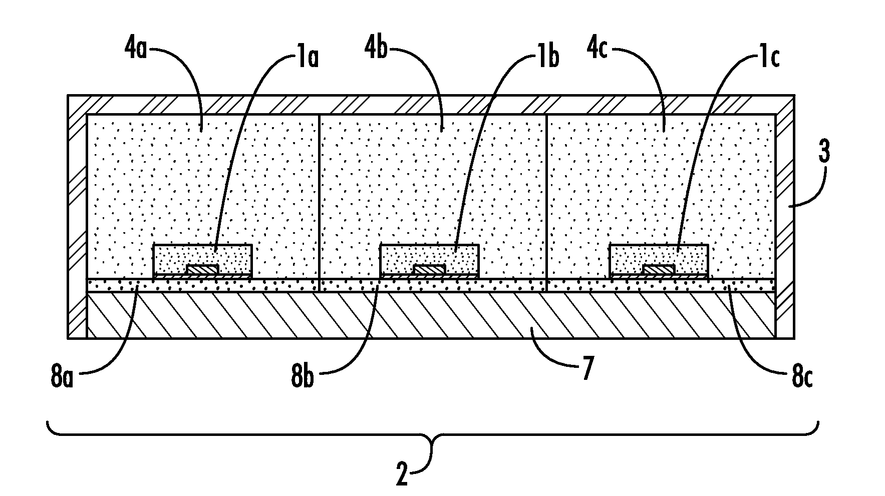
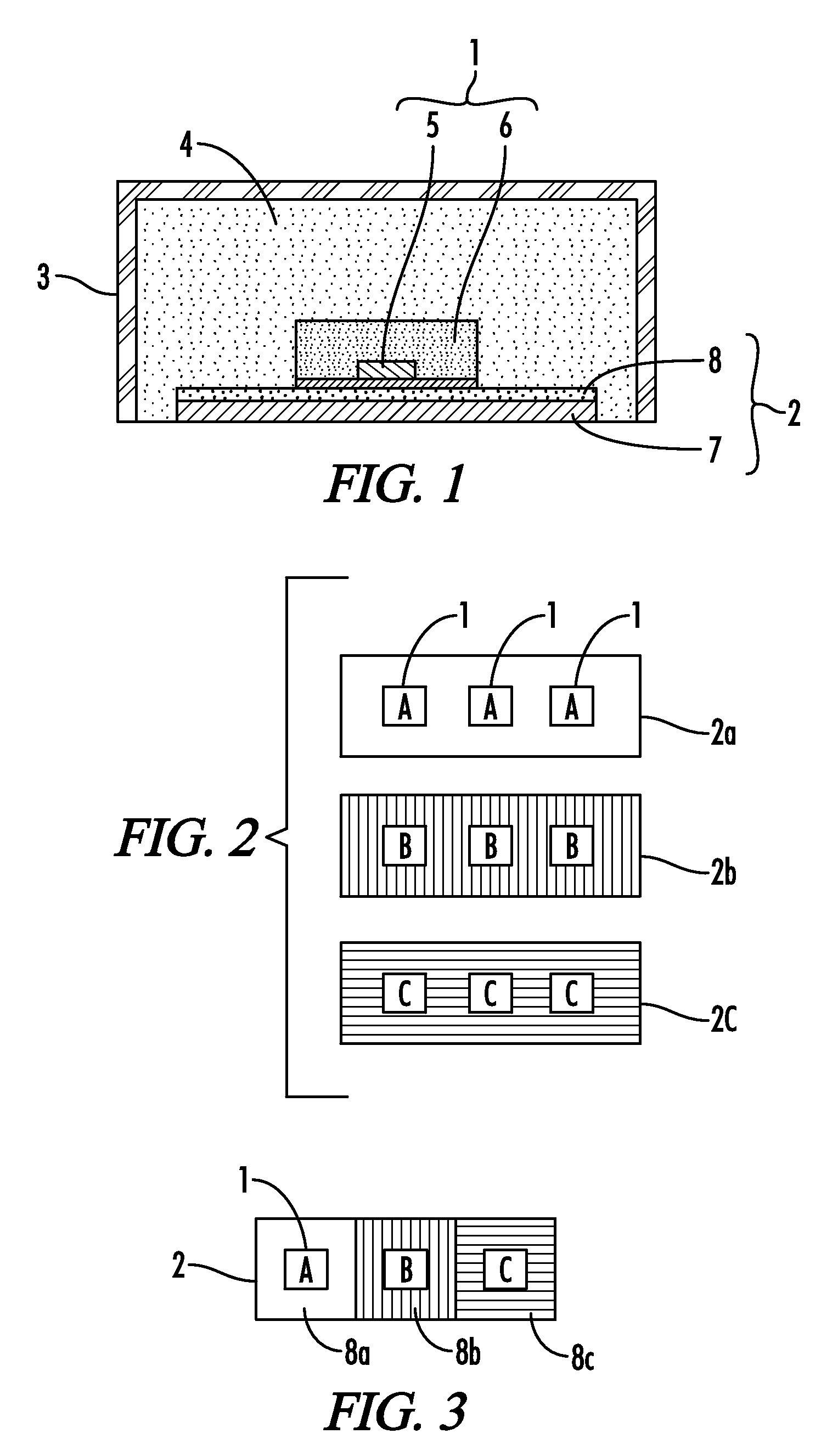
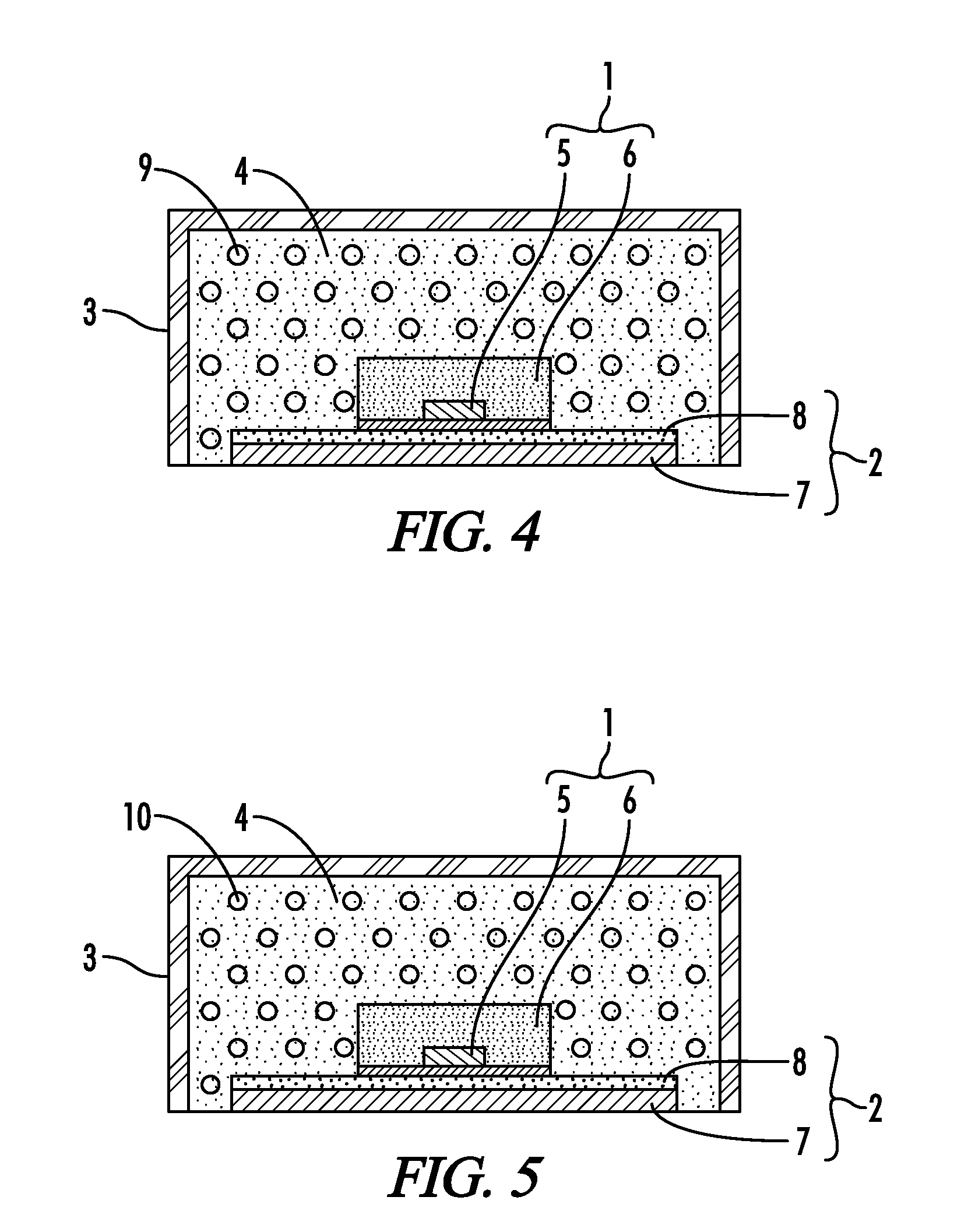
[0037]FIG. 1 shows a structure of a first embodiment of the present invention. As shown in FIG. 1, an illumination device includes a light emitting device 1 such as for example an LED 1, an LED mounting substrate 2 on which the LED is mounted, a case 3 for storing them, and a translucent filling material 4 such as resin 4 (e.g., silicon) for filling the inside of the case 3. The translucent filling material 4 may in fact be entirely transparent in alternative embodiments.

[0038]The LED 1 comprising the light emitting device may be provided with a blue LED chip 5 which emits light with a wavelength of approximately 380 to 480 nm, the blue LED chip sealed with a resin 6 (e.g., silicon) containing a phosphor. One sealing resin 6 may encompass a plurality of LED chips 5.

[0039]The substrate 2 on which the LED 1 is mounted comprises a base material 7, and a coating (ink) 8 applied on the base material 7. The LED 1 and the substrate 2 are embedded and hermetically sealed in the resin 4. The...


PUM


Abstract

An illumination assembly is provided which is capable of correcting a color temperature. The assembly generally comprises a substrate and a light emitting device mounted on the substrate that further comprises a light emitting element and a resin containing a phosphor excitable by light emitted from the light emitting element. A reflectance factor of the substrate may be set corresponding to light emitted from the light emitting device, such that the light emitted by the light emitting device complies with a desired light emission for the illumination assembly. A translucent filling resin or translucent coating resin may further be applied on the light emitting device and the substrate, the translucent resin having a refractive index and correspondingly operable to suppress variations in color temperature. The assembly may comprise a plurality of light emitting devices having variable light color temperatures, wherein a plurality of substrate coatings may be provided having reflectance factors corresponding to the associated light color temperatures. One or more translucent resins may be applied on light emitting devices as desired to further suppress variations in color temperature.

Description

[0001]A portion of the disclosure of this patent document contains material that is subject to copyright protection. The copyright owner has no objection to the reproduction of the patent document or the patent disclosure, as it appears in the U.S. Patent and Trademark Office patent file or records, but otherwise reserves all copyright rights whatsoever.CROSS-REFERENCES TO RELATED APPLICATIONS[0002]This application claims benefit of the following patent application which is hereby incorporated by reference: Japanese Patent Application No. JP2008-113315 filed Apr. 24, 2008STATEMENT REGARDING FEDERALLY SPONSORED RESEARCH OR DEVELOPMENT[0003]Not ApplicableREFERENCE TO SEQUENCE LISTING OR COMPUTER PROGRAM LISTING APPENDIX[0004]Not ApplicableBACKGROUND OF THE INVENTION[0005]The present invention relates to an illumination device using a light emitting element such as a light emitting diode (hereinafter referred to as “LED”).[0006]In a conventional illumination device using a light emitti...

Claims


Application Information

Patent Timeline
Patent Type & Authority Applications(United States)
IPC IPC(8): H01L27/15H01L33/00H01L33/50H01L33/52H01L33/60
CPCH01L25/0753H01L33/60H01L33/52H01L33/50H01L2924/0002H01L2924/00
Inventor TAKASHIMA, JUNKANAI, NORIO
Owner PANASONIC INTELLECTUAL PROPERTY MANAGEMENT CO LTD
Why Eureka
Try Eureka