
Direct Current Measuring Device With Wide Measuring Range, Electro-Technical Unit Comprising One Such Measuring Device and Switchgear Unit Having One Such Electro-Technical Unit

a technology of direct current and measuring device, which is applied in the direction of measurement devices, measurement using dc-ac conversion, instruments, etc., can solve the problems of erroneous signal supply of measuring device, erroneous response of measuring device, and no longer following the previous linear response curve of measuring devi

Active Publication Date: 2010-01-07
SCHNEIDER ELECTRIC IND SAS
View PDF9 Cites 23 Cited by
  • Summary
  • Abstract
  • Description
  • Claims
  • Application Information

AI Technical Summary

Benefits of technology

[0011]The object of the invention is therefore to remedy the shortcomings of the state of the art so as to propose a sensitive direct current measuring device providing a wide measuring range.

Problems solved by technology

However, when the electric currents exceed a certain intensity, the response of the measuring device no longer follows the previous linear response curve.
Following saturation phenomena observed in particular in the magnetic structure and / or in the magnetic sensor and / or in the measuring channel, the measuring device response becomes erroneous.
The signals respectively sent by the magnetic sensors are no longer proportional to the current intensity flowing in the conductor and the signal supplied by the measuring device is erroneous.
High-intensity electric currents cannot be measured with this type of measuring device.
However, this type of solution presents the drawback of not being sufficiently sensitive to low-intensity electric currents.

Method used


Image

  • Direct Current Measuring Device With Wide Measuring Range, Electro-Technical Unit Comprising One Such Measuring Device and Switchgear Unit Having One Such Electro-Technical Unit
  • Direct Current Measuring Device With Wide Measuring Range, Electro-Technical Unit Comprising One Such Measuring Device and Switchgear Unit Having One Such Electro-Technical Unit
  • Direct Current Measuring Device With Wide Measuring Range, Electro-Technical Unit Comprising One Such Measuring Device and Switchgear Unit Having One Such Electro-Technical Unit

Examples


Embodiment Construction

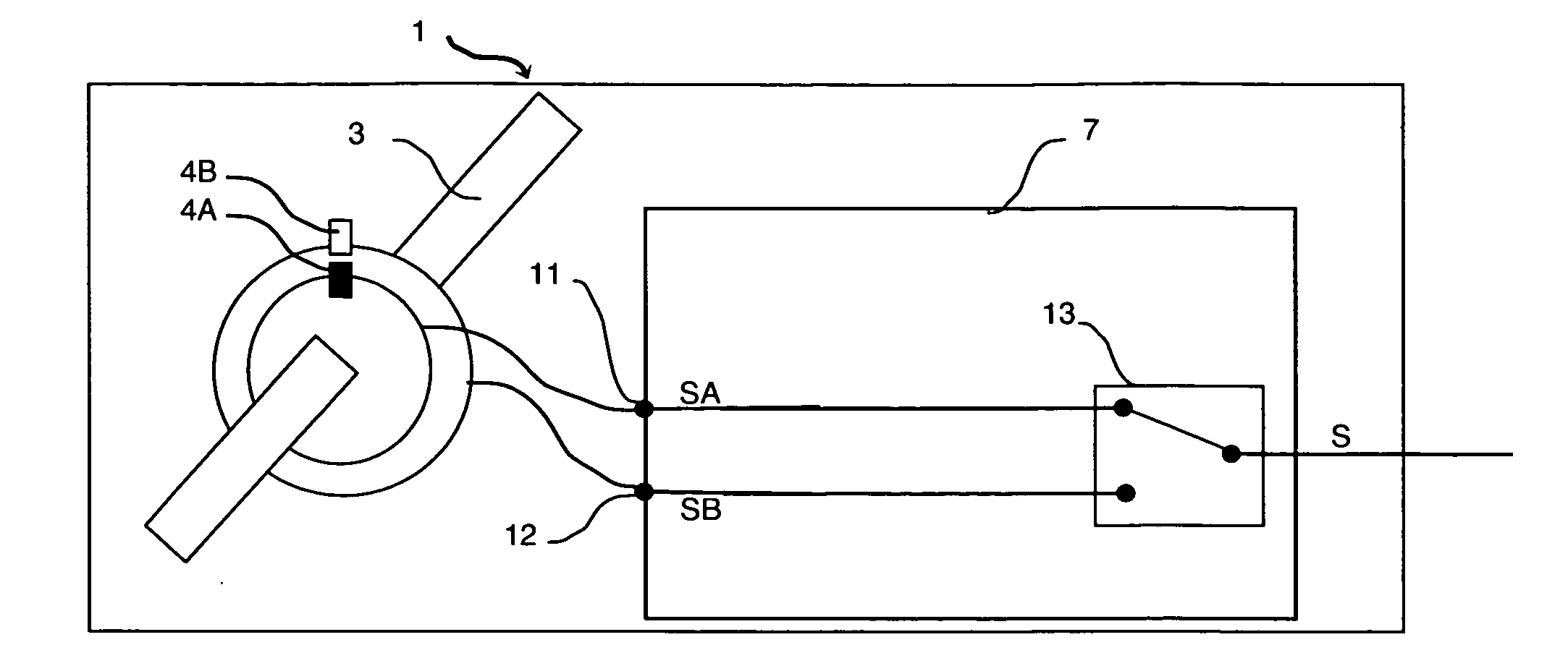
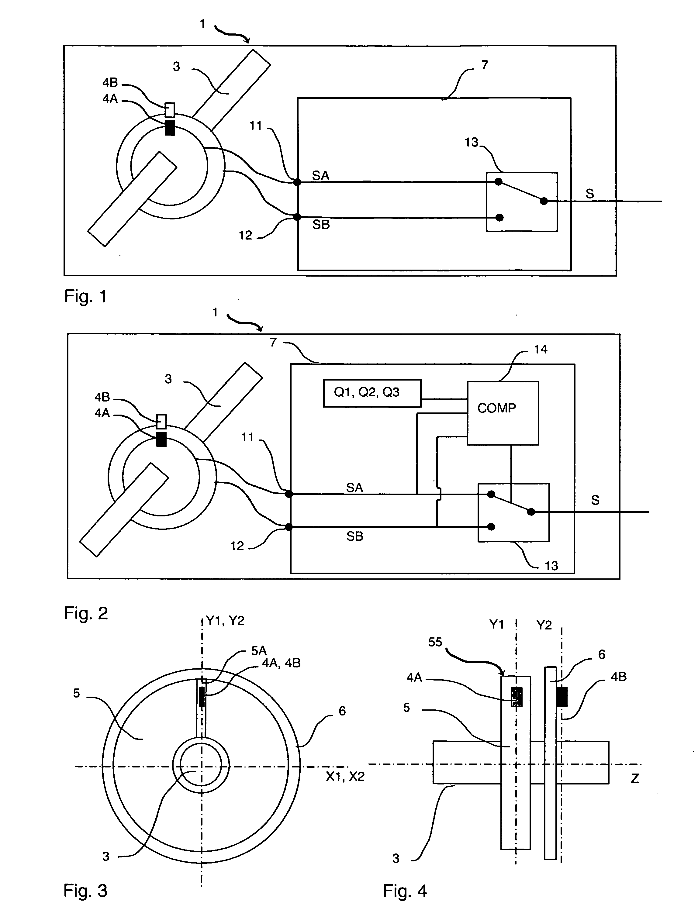
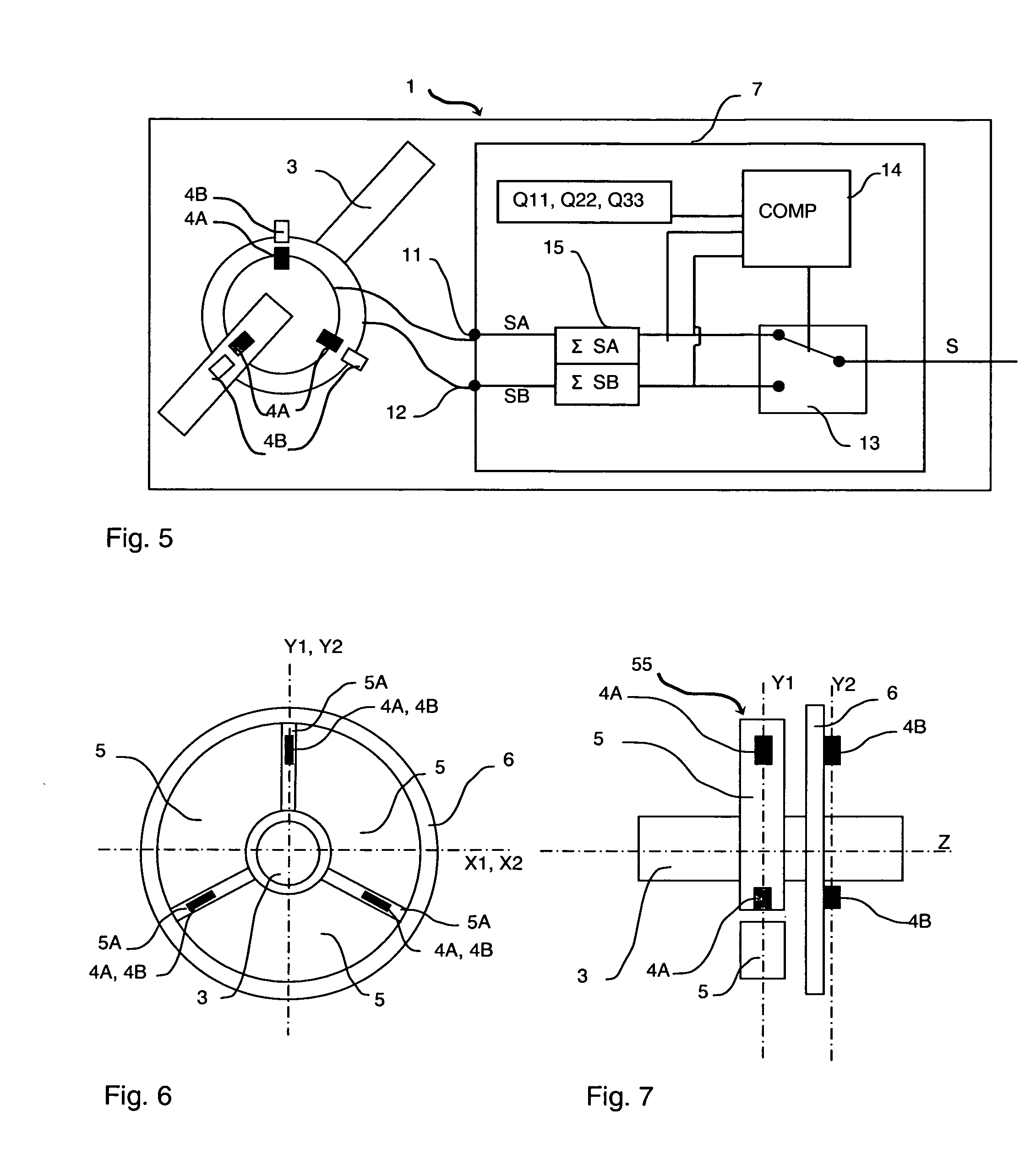
[0036]According to a first embodiment of the invention, the direct current measuring device 1 comprises magnetic sensors 4A, 4B sensitive to a magnetic field generated by an electric current I flowing in a conductor 3. These magnetic sensors are preferably Hall effect sensors. It can however be envisaged to use magnetoresistors.

[0037]As represented in FIGS. 3 and 4, these magnetic sensors are arranged on two profiles 55, 6.

[0038]At least one first magnetic sensor 4A is integrated in a first magnetic profile 55 designed to surround an electric conductor 3. The first magnetic profile comprises at least one elongate section 5 made from ferromagnetic material with high magnetic permeability. The section is configured such that these two ends are placed facing one another. A space is present between these two ends. This space forms an air-gap 5A in which a magnetic sensor 4A is placed. According to this example of embodiment, the first magnetic sensor 4A is arranged in a first plane X1Y1...


PUM


Abstract

A direct current measuring device comprising at least one first magnetic sensor and at least one second magnetic sensor sensitive to a magnetic field generated by an electric current flowing in a conductor. The measuring device comprises a processing unit connected to the magnetic sensors and designed to generate an output signal dependent on the measurement signals supplied by the magnetic sensors. Said processing unit comprises selection means supplying the output signal dependent, for weak electric currents on the first measurement signals from at least one first magnetic sensor, and dependent, for strong electric currents, on the second measurement signals from at least one second magnetic sensor.

Description

BACKGROUND OF THE INVENTION[0001]The invention relates to a direct current measuring device comprising at least one first magnetic sensor and at least one second magnetic sensor, said magnetic sensors being sensitive to a magnetic field generated by an electric current flowing in a conductor. The current measuring device comprises a processing unit connected to the magnetic sensors and designed to generate an output signal dependent on the measurement signals supplied by the magnetic sensors and representative of said electric current flowing in the conductor.[0002]The invention also relates to an electro-technical unit comprising a conversion card connected to trip means designed to send tripping orders. Finally the invention also relates to a switchgear unit comprising an opening mechanism for opening electric contacts and a control relay connected to an electro-technical unit according to the invention.STATE OF THE ART[0003]The use of direct current measuring devices is extremely...

Claims


Application Information

Patent Timeline
IPC IPC(8): G01R15/18
CPCG01R15/202G01R15/207G01R15/205G01R15/08
Inventor SERPINET, MARCVINCENT, FRANCOIS
Owner SCHNEIDER ELECTRIC IND SAS
Learn More