Methods and configurations of lc combined transformers and effective utilizations of cores therein

US20100001822A1Inactive Publication Date: 2010-01-07LI CHUN +2

Image

  • Methods and configurations of lc combined transformers and effective utilizations of cores therein
  • Methods and configurations of lc combined transformers and effective utilizations of cores therein
  • Methods and configurations of lc combined transformers and effective utilizations of cores therein

Examples


Embodiment Construction

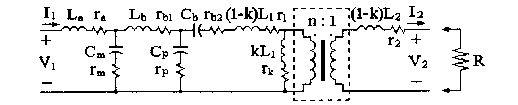
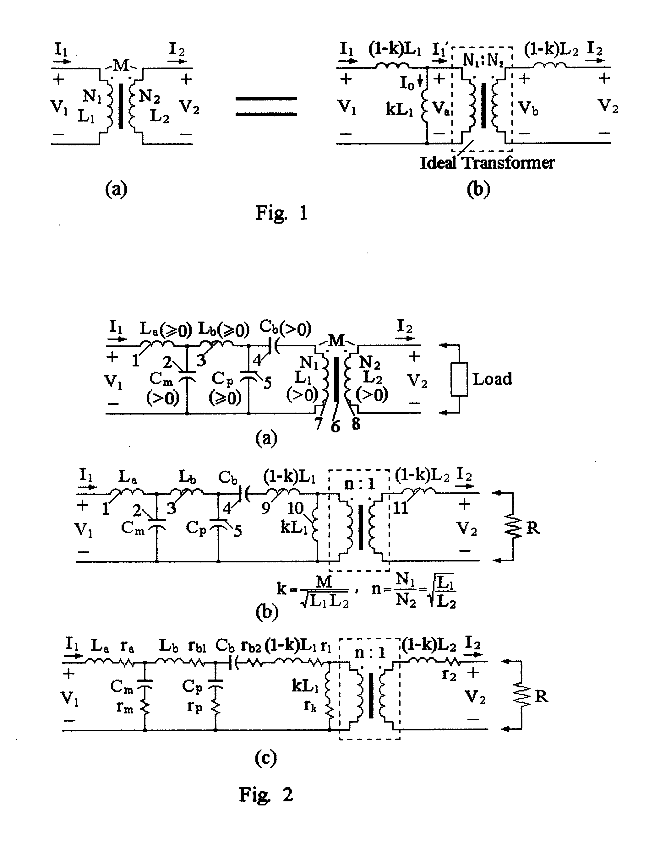
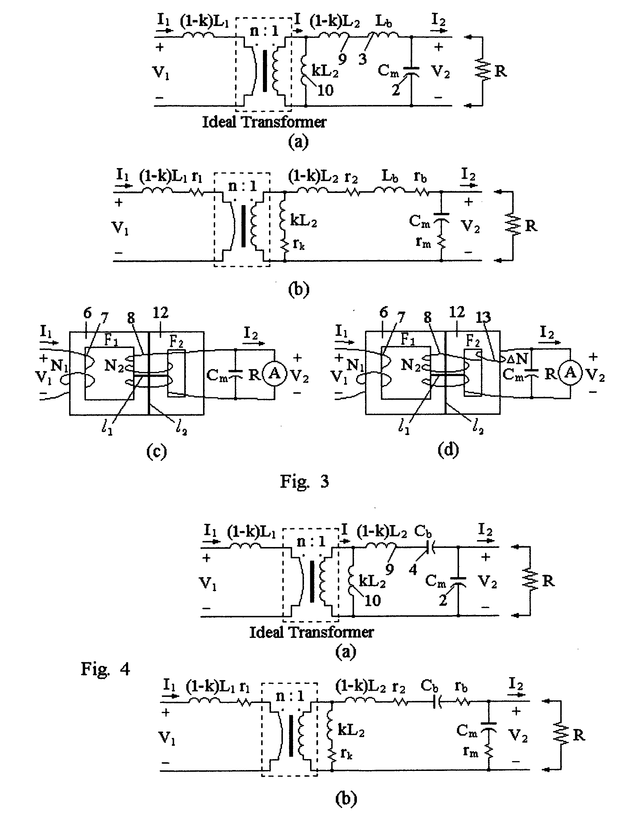
[0018]The general circuitry arrangement of the LC combined transformer is illustrated as in FIG. 2(a), with the load not included. Circuit components 1 and 3 are inductances La and Lb, with inductance value >0 meaning positive, and the value=0 meaning short-circuited. Circuit components 2, 4 and 5 are capacitances Cm, Cb and Cp, with capacitance value >0 meaning positive (including C→+∞, short-circuited), and the value=0 meaning open-circuited. 6 is the core magnetic circuit of the mutual inductor, 7 its primary winding N1 (with inductance L1>0), and 8 its secondary winding N2 (with inductance L2>0) and, 6,7 and 8 constitute a mutual inductor or conventional transformer. All the circuit components and the mutual inductor herein can be real devices, although their magnitudes or values may be worked out respectively by one or more components based on the principles of series-parallel connections, with their application equivalent for the definition herein, and with the corresponding p...


PUM


Abstract

This invention presents the LC combined transformer, a combination of capacitances, inductances and an electrically-isolated mutual inductor, i.e. conventional transformer. To improve the imperfections of the widely-used transformers, by means of the simplest passive-circuit design of perfectly-functionally mating mutual capacitors with the mutual inductor, the invention achieves optimal characteristics of current or / and voltage conversions, with a new property of waveform conversion from square-wave to quasi-sinusoid. The ideal current transformers herein are suited to sinusoidal current measurements, the ideal voltage transformers suited to sinusoidal voltage measurements, and they all could be upgraded to ideal transformers, capable of current and voltage conversions. They can also be designed as both power transferable and waveform convertible, applicable in power electronics. Herein also states the design approach of integrated inductor and mutual inductor and the usage of push-pull inductor, materials being fully utilized and sizes greatly decreased.

Description

FIELD OF THE INVENTION[0001]This invention relates to a transformer which is a combination of capacitances, inductances and also an electrically-isolated mutual inductor (namely, conventional transformer), and called LC combined transformer.BACKGROUND OF THE INVENTION[0002]It is well known that the electric transformer, i.e. the conventional voltage / current transformer, widely-used in electrical engineering is actually a mutual inductor with its coupling coefficient k less than but close to 1. In order to address this issue more clearly, for the time being, let's review its electric characteristic equations when neglecting power loss. As the port variables of a mutual inductor supposed as corresponding to those illustrated in FIG. 1(a), in electrical theory, its electrical characteristic equations in a sinusoidal steady-state circuit are presented as{V1=jωL1I1-jωMI2V2=jωMI1-jωL2I2(1)(2)where L1 and L2 respectively represent self-inductances of the primary winding and the secondary w...

Claims


Application Information

Patent Timeline
07 Jan 2010
Publication
US20100001822A1
IPC
H01F17/00
CPC
H01F3/12; H01F38/16; H01F27/385
Inventors
LI, CHUN; LI, RAN RAN