
Shift register apparatus and method thereof

a technology of shift register and register, which is applied in the direction of pulse counter, counting chain synchronous pulse counter, and increasing modification, etc., can solve the problem of reducing the utilization reliability of the equipment, and achieve the effect of improving the utilization reliability of the nmos transistor

Inactive Publication Date: 2010-01-07
CHUNGHWA PICTURE TUBES LTD
View PDF9 Cites 34 Cited by
  • Summary
  • Abstract
  • Description
  • Claims
  • Application Information

AI Technical Summary

Benefits of technology

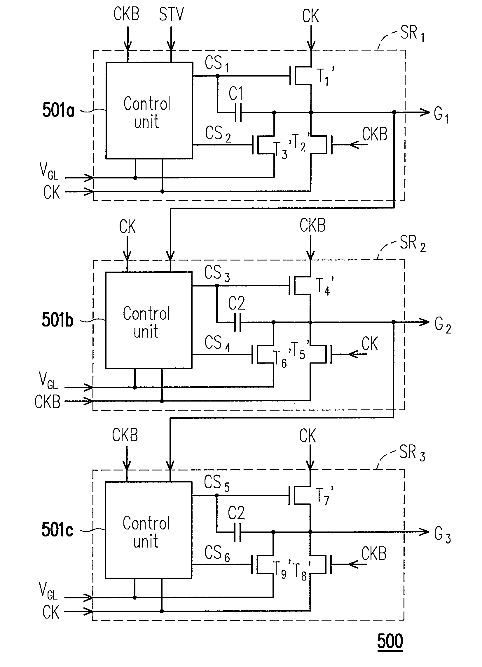
[0016]Accordingly, to cope with increasing demand of narrow frame panels, and to improve a utilization reliability of NMOS transistors within a shift register that used for pulling down voltage levels of output scan signals thereof to a low level gate voltage, the present invention provides a shift register apparatus directly disposed on a glass substrate of an LCD panel. The shift register apparatus includes a plurality of shift registers connected in serial. Each of the shift registers includes a first transistor, a second transistor, a third transistor, an energy storage device and a control unit.
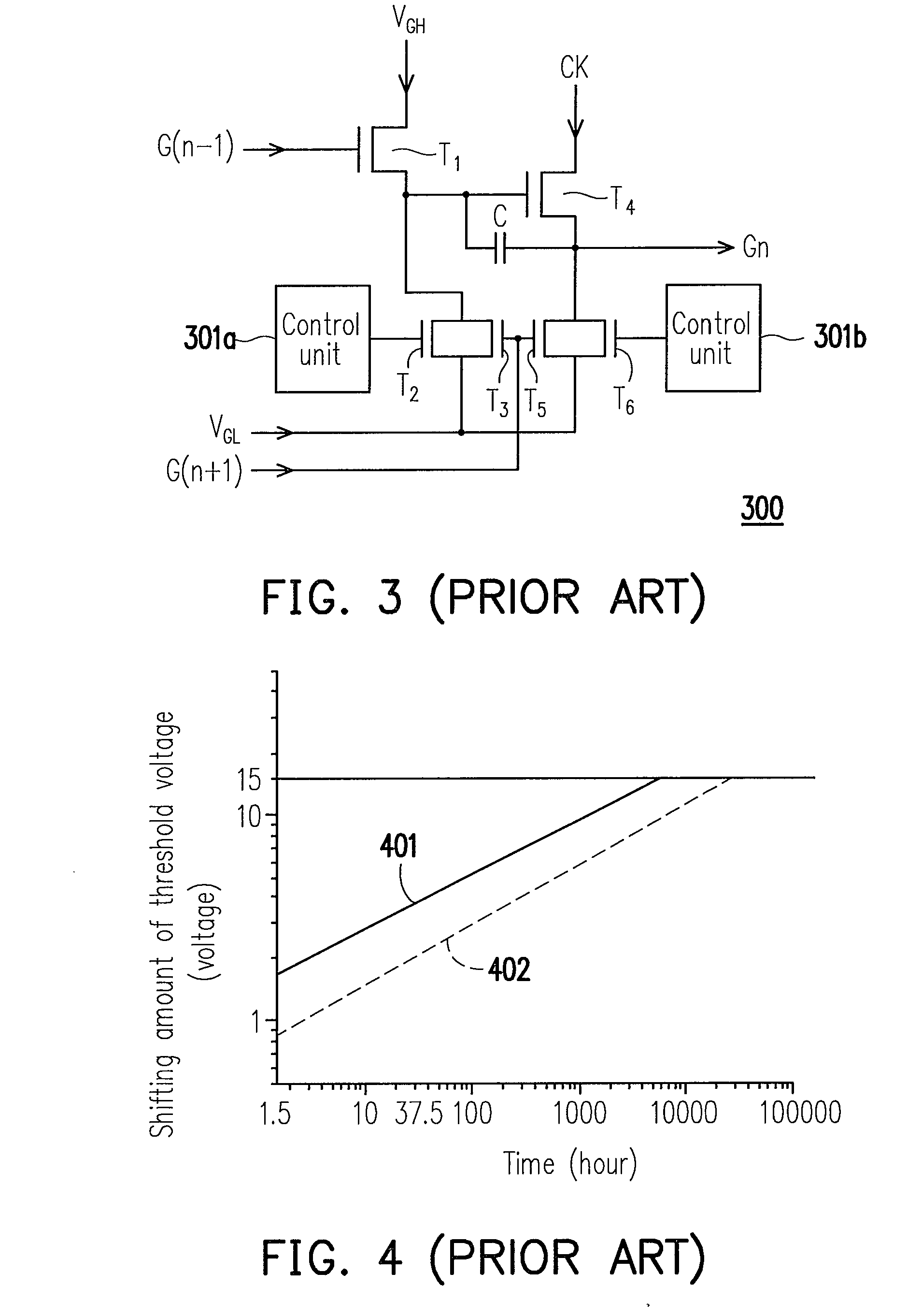
[0027]Therefore, shifting amounts of the threshold voltages of the two NMOS transistors used for pulling down the level of the scan signal output from the shift register to the low level gate voltage trend to be flat, and accordingly utilization reliability of the NMOS transistors can be greatly improved. In addition, since only one control unit is needed to dispose in each shift register so that the layout area of the whole shift register apparatus can be reduced, so as to cope with an increasing demand of narrow frame panels.

Problems solved by technology

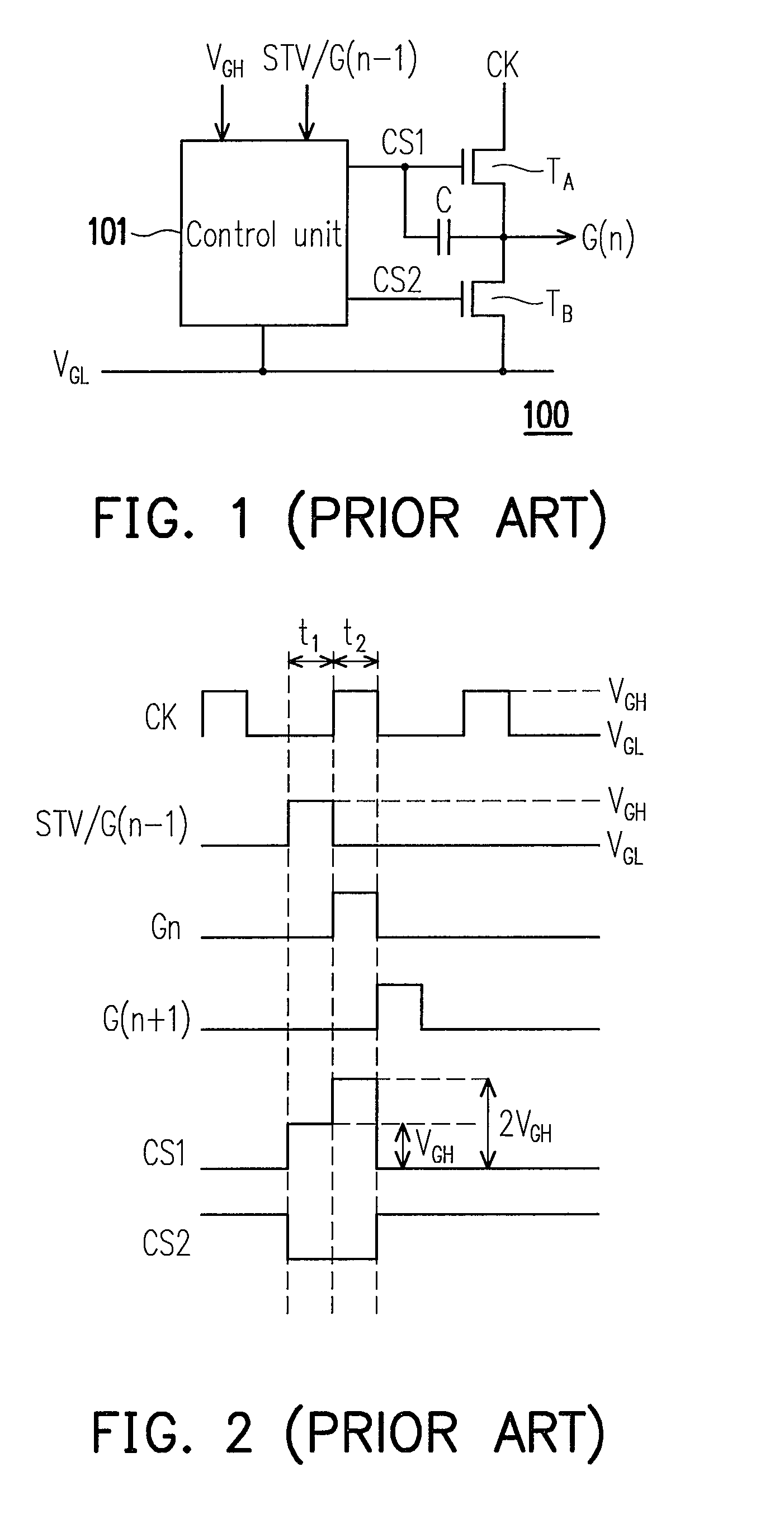
In such case, the NMOS transistor TB may be aged quickly due to a long time turning on state thereof, and accordingly utilization reliability thereof is decreased.

Method used


Image

  • Shift register apparatus and method thereof
  • Shift register apparatus and method thereof
  • Shift register apparatus and method thereof

Examples


Embodiment Construction

[0038]The technical functions to be achieved by the present invention are mainly to improve a utilization reliability of NMOS transistors used for pulling down voltage levels of all scan signals output by the shift registers to a low level gate voltage, and to cope with an increasing demand of narrow frame panels. In the following content, technical characteristics of the present invention are described in detail for those skilled in the art.

[0039]FIG. 5 is a circuit block diagram illustrating a shift register apparatus 500 according to an embodiment of the present invention. Referring to FIG. 5, the shift register apparatus 500 of the present embodiment is directly disposed on a glass substrate of an LCD panel (not shown), and includes a plurality of shift registers (with a number thereof being equal to a number of scan lines of the LCD panel) for sequentially generating scan signals to the corresponding scan lines, so as to activate or deactivate pixels coupled to the scan lines.

[...


PUM


Abstract

A shift register apparatus and a method thereof are provided. The technique manner submitted by the present invention utilizes two NMOS transistors for pulling down the voltage level of the scan signals output by the shift registers within the shift register apparatus to the low level gate voltage, wherein one of the NMOS transistors is controlled by a control unit, and the other NMOS transistor is controlled by a clock signal or the inverted clock signal provided to the shift registers. Therefore, shifting amount of the threshold voltage of those NMOS transistors can trend to be flat, and the reliability of those NMOS transistors can be promoted. In addition, since only one control unit is needed to dispose in each shift register so that the layout area of whole shift register apparatus can be reduced, and the panel with narrow frame size also can be achieved by the present invention.

Description

CROSS-REFERENCE TO RELATED APPLICATION[0001]This application claims the priority benefit of Taiwan application serial no. 97124750, filed on Jul. 1, 2008. The entirety of the above-mentioned patent application is hereby incorporated by reference herein and made a part of specification.BACKGROUND OF THE INVENTION[0002]1. Field of the Invention[0003]The present invention relates to a shift register apparatus and a method thereof. More particularly, the present invention relates to a shift register apparatus and a method thereof which may improve a utilization reliability of NMOS transistors used for pulling down voltage levels of output scan signals within the shift register apparatus to a low level gate voltage, and may cope with an increasing demand of narrow frame panels.[0004]2. Description of Related Art[0005]Recently, with booming development of the semiconductor technology, portable electronic devices and flat panel displays are widely used. Among various kinds of panel display...

Claims


Application Information

Patent Timeline
IPC IPC(8): H03K23/46
CPCG09G3/3677H03K19/00315G11C19/28G09G2310/0286
Inventor SHIH, CHIH-JENHSU, CHUN-YUANKUO, CHE-CHENGYU, CHUN-KUO
Owner CHUNGHWA PICTURE TUBES LTD
Learn More