Control of the positional relationship between a sample collection instrument and a surface to be analyzed during a sampling procedure with image analysis

a positional relationship and sample collection technology, applied in the field of sampling means and methods, can solve problems such as poor collection results, and achieve the effect of improving the accuracy of sampling results

Active Publication Date: 2010-01-07
UT BATTELLE LLC
View PDF16 Cites 20 Cited by
  • Summary
  • Abstract
  • Description
  • Claims
  • Application Information

AI Technical Summary

Problems solved by technology

In other words, there is a desirable spatial assignment which exists between the emitter, the collection instrument and the surface to be analyzed so that if the surface is not accurately positioned in a location (e.g. within a predetermined plane) in which the surface is intended to be positioned, poor collection results are likely to be obtained.

Method used


Image

  • Control of the positional relationship between a sample collection instrument and a surface to be analyzed during a sampling procedure with image analysis
  • Control of the positional relationship between a sample collection instrument and a surface to be analyzed during a sampling procedure with image analysis
  • Control of the positional relationship between a sample collection instrument and a surface to be analyzed during a sampling procedure with image analysis

Examples


Embodiment Construction

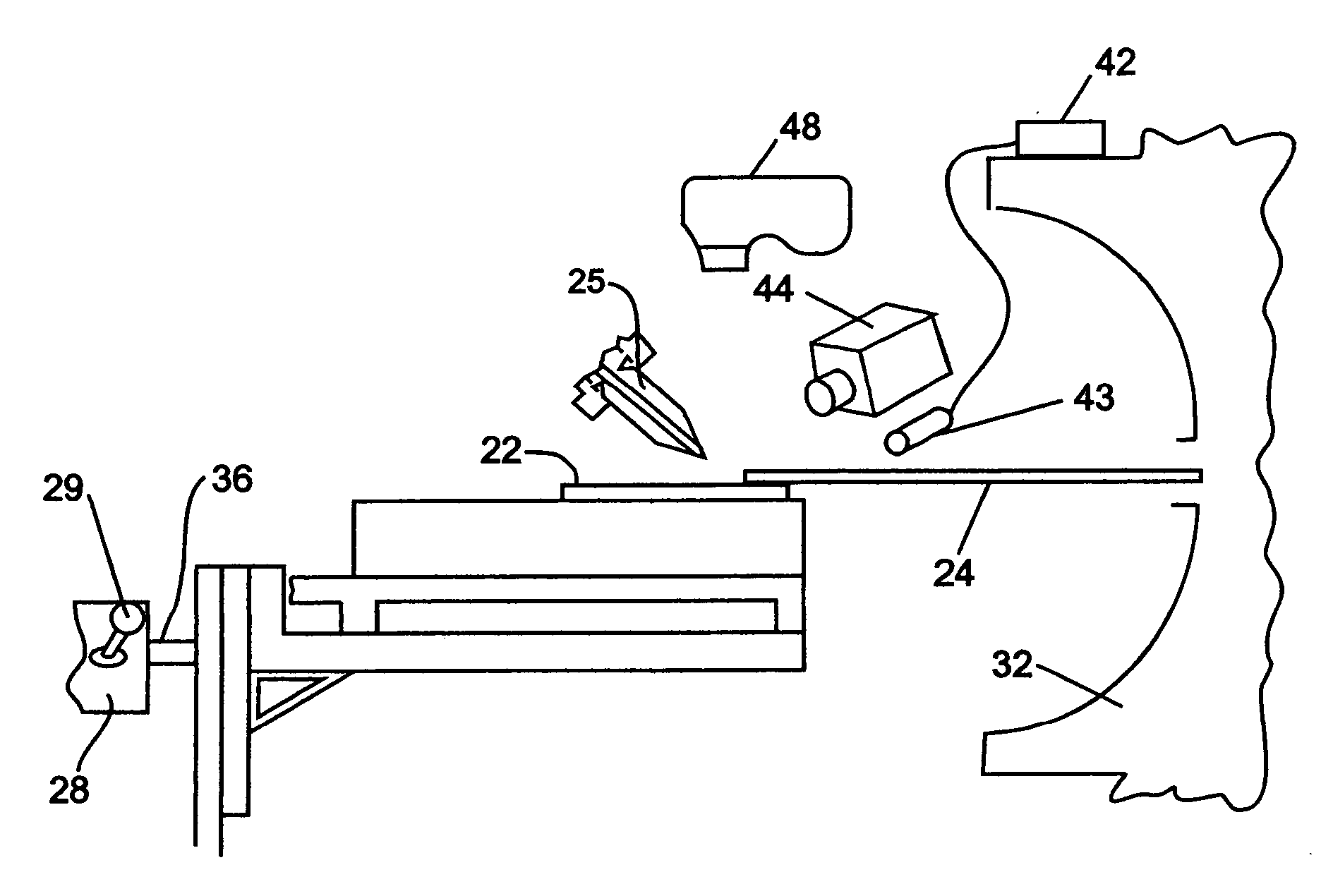
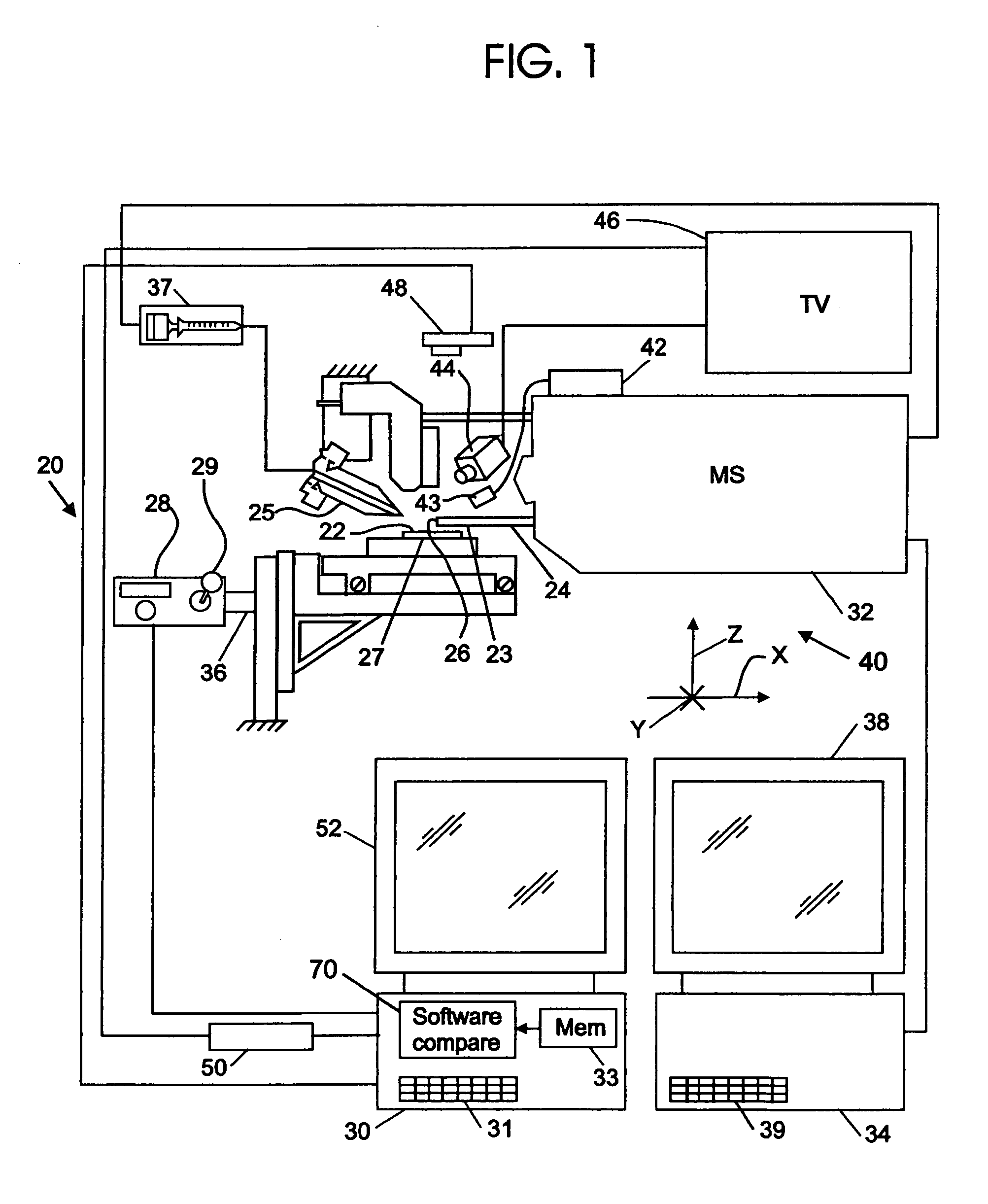
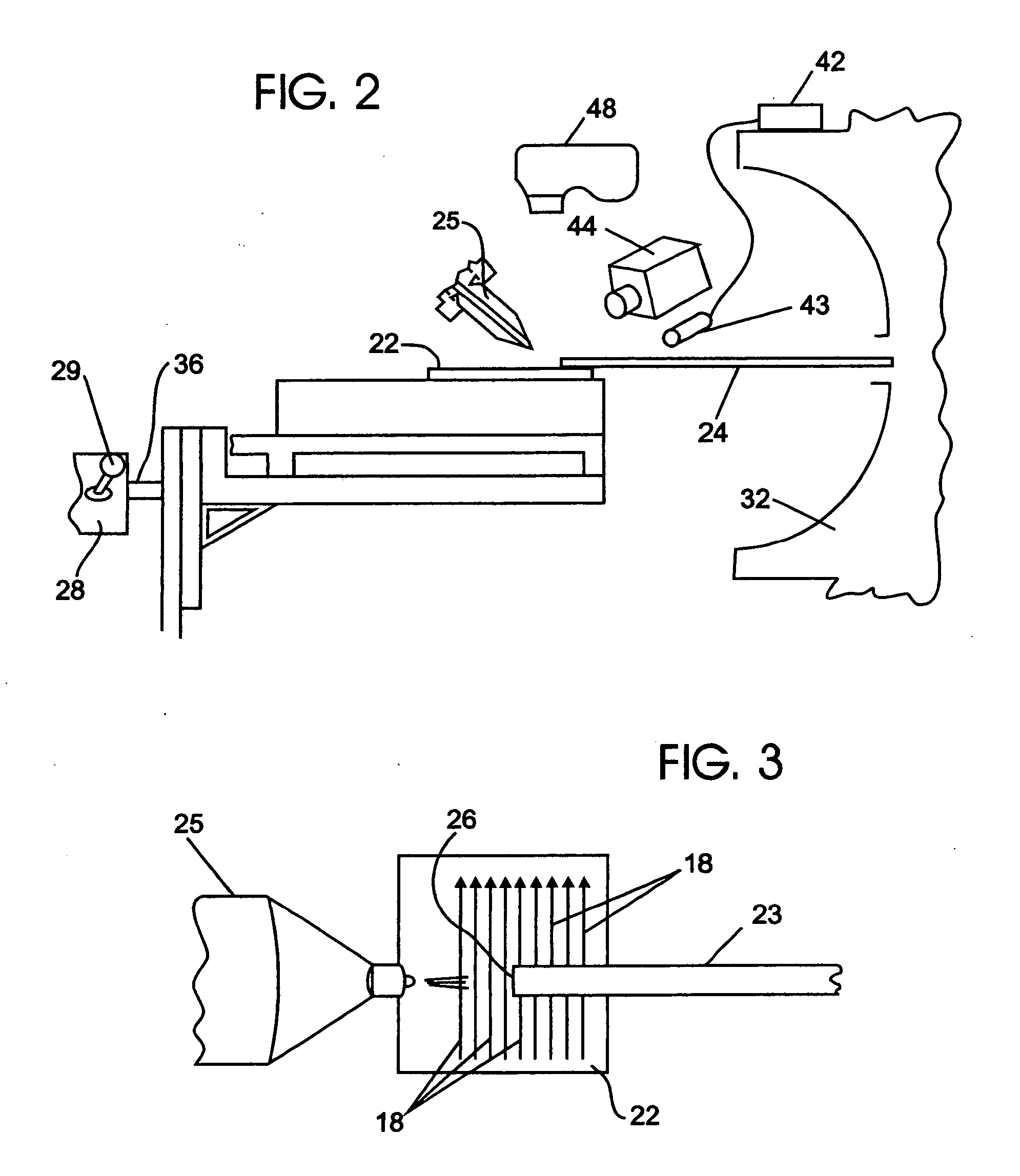
[0026]Turning now to the drawings in greater detail and considering first FIG. 1, there is schematically illustrated an example of an embodiment, generally indicated 20, of a desorption electrospray (DESI) system within which features of the present invention are embodied for purposes of obtaining samples from at least one spot, or area, of a surface 22 (embodying a surface to be sampled) for subsequent analysis. Although the surface 22 to be sampled can, for example, be an array whose samples are desired to be analyzed with a mass spectrometer 32, the system 20 can be used to sample any of a number of surfaces of interest. Accordingly, the principles of the invention can be variously applied.

[0027]The system 20 of the depicted example includes a collection instrument in the form of a sampling probe 24 (and an associated DESI emitter 25) comprising a capillary tube 23 which terminates at a tip 26 which is positionable adjacent to the surface 22. During a sampling process, for exampl...


PUM


Abstract

A system and method utilizes an image analysis approach for controlling the collection instrument-to-surface distance in a sampling system for use, for example, with mass spectrometric detection. Such an approach involves the capturing of an image of the collection instrument or the shadow thereof cast across the surface and the utilization of line average brightness (LAB) techniques to determine the actual distance between the collection instrument and the surface. The actual distance is subsequently compared to a target distance for re-optimization, as necessary, of the collection instrument-to-surface during an automated surface sampling operation.

Description

[0001]This invention was made with Government support under Contract No. DE-AC05-000R22725 awarded by the U.S. Department of Energy to UT-Battelle, LLC, and the Government has certain rights to the invention.BACKGROUND OF THE INVENTION[0002]This invention relates generally to sampling means and methods and relates, more particularly, to the means and methods for obtaining samples from a surface to be analyzed for subsequent analysis.[0003]The sampling collection techniques with which this invention is concerned involve the positioning of a collection instrument in relatively close proximity to a surface to be analyzed, or sampled, for purposes of gathering an amount (e.g. ions) of the surface for analysis. An example of one such collection technique is used in conjunction with desorption electrospray ionization (DESI) mass spectrometry, but other techniques that require collection of analytes or particles from a surface, such as desorption atmospheric pressure chemical ionization (D...

Claims


Application Information

Patent Timeline
Patent Type & Authority Applications(United States)
IPC IPC(8): G06K9/00
CPCH01J49/0459
Inventor VAN BERKEL, GARY J.KERTESZ, VILMOS
Owner UT BATTELLE LLC
Why Eureka
Try Eureka