Image forming apparatus
a technology of forming apparatus and forming parts, which is applied in the direction of electrographic process apparatus, instruments, optics, etc., can solve the problems of affecting the transfer part, and affecting the overall size of the apparatus
- Summary
- Abstract
- Description
- Claims
- Application Information
AI Technical Summary
Benefits of technology
Problems solved by technology
Method used
Image
Examples
exemplary embodiment 1
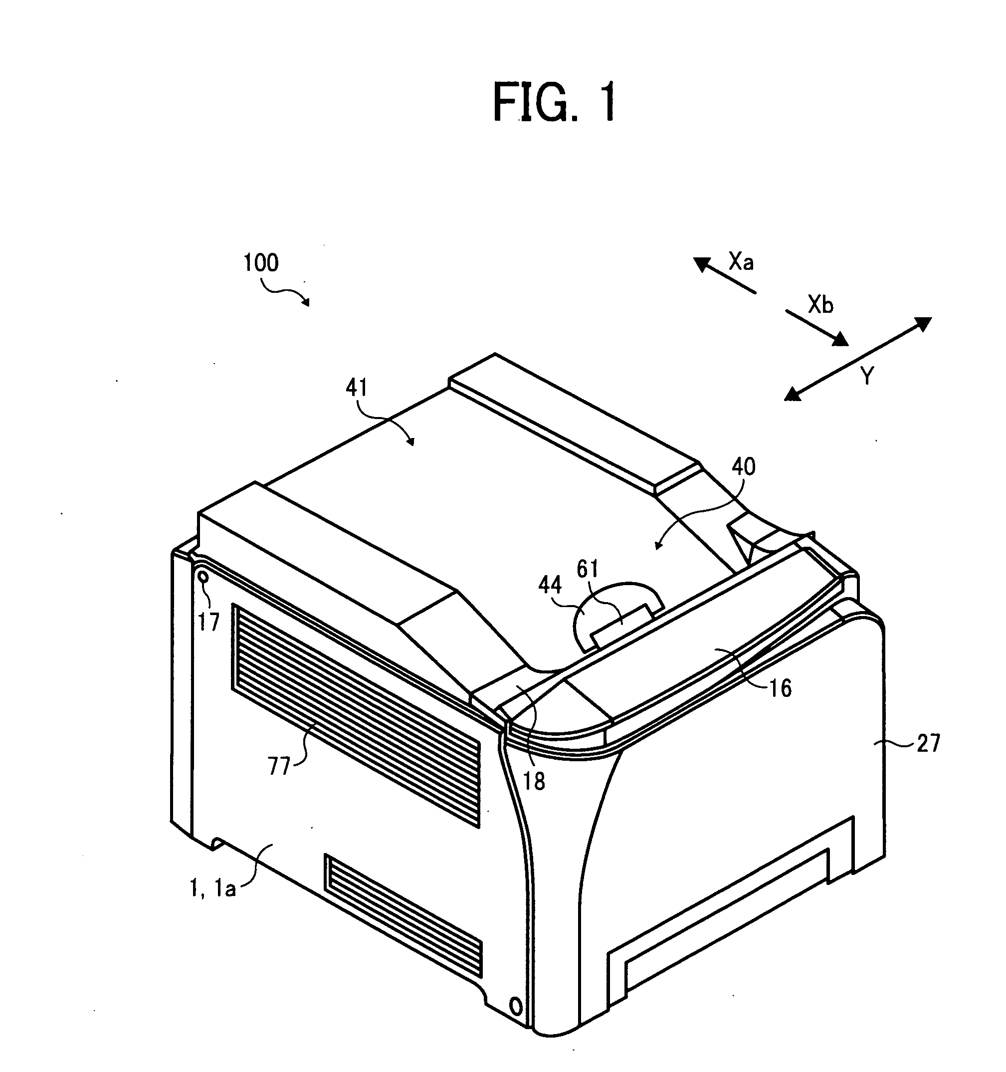
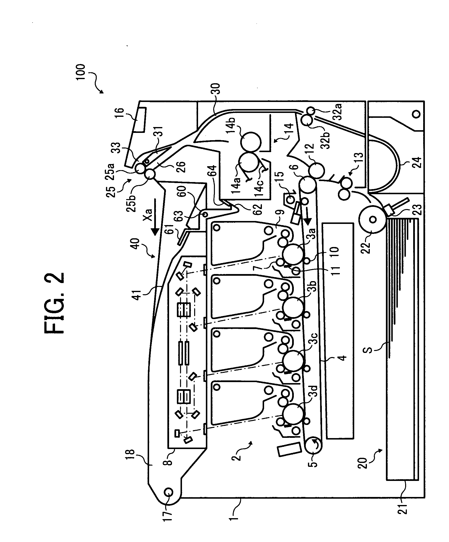
[0057]Referring to FIGS. 1 through 3, descriptions are given of a schematic configuration and operations of an image forming apparatus 100 according to Example Embodiment 1 of the present patent application.
[0058]FIG. 1 illustrates a perspective view of the image forming apparatus 100, and FIG. 2 illustrates a vertical cross-section of an interior of the image forming apparatus 100 of FIG. 1.
[0059]The image forming apparatus 100 can be any of a copier, a printer, a facsimile machine, a plotter, and a multifunction printer including at least one of copying, printing, scanning, plotter, and facsimile functions. In this non-limiting exemplary embodiment, the image forming apparatus 100 functions as a full-color printing machine for electrophotographically forming a toner image based on image data on a recording medium (e.g., a transfer sheet).
[0060]The toner image is formed with four single toner colors, which are yellow, cyan, magenta, and black. Reference symbols “Y”, “C”, “M”, and “...
example embodiment 1
[0134]Referring to FIG. 7A, a description is given of the image forming apparatus 100 according to Example Embodiment 1 of the present patent application.
[0135]In FIG. 7A illustrating the configuration according to Example Embodiment 1, the image forming apparatus 100 includes hollow portions 67 and 69.
[0136]The hollow portion 67 is located above the fixing unit 14, between the fixing unit 14 and the sheet reverse path 30. The hollow portion 67 is surrounded by the upper fixing guide plate 70 and the outlet fixing guide plate 71. Both of the upper fixing guide plate 70 and the outlet fixing guide plate 71 serve as multiple guide members.
[0137]The hollow portion 69 is surrounded by the lower fixing guide plate 75. The lower fixing guide plate 75 is also included in the multiple guide members.
[0138]An air current that may include vapor is generated in a heated area of the fixing unit 14 during image forming and flows to the hollow portions 67 and 69 or to inner walls of the upper fixi...
example embodiment 2
[0141]Referring to FIG. 8, a description is given of the image forming apparatus 100 according to Example Embodiment 2 of the present patent application.
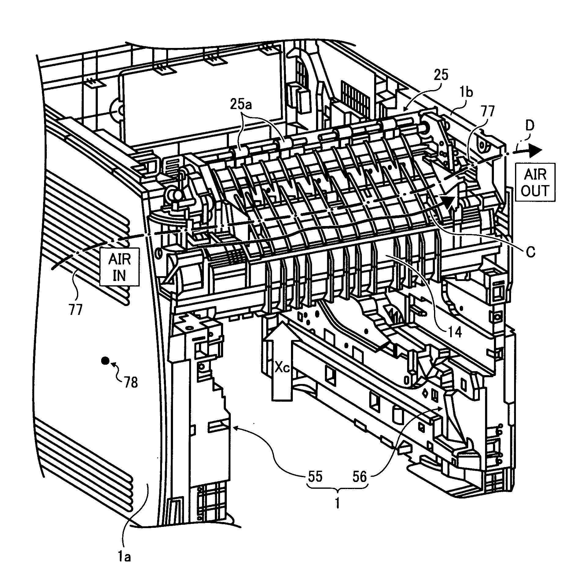
[0142]As shown in FIG. 8, the hollow portion 67 extends to enable an air current indicated by arrow B to flows in the hollow portion 67 in a direction substantially perpendicular to the direction Xc that is a direction of conveyance of the transfer sheet S. That is, the air current B travels in the hollow portion 67.
[0143]As previously shown in FIG. 4, the louver 77 is formed on each of the left external cover 1a of the left frame 55 and the right external cover 1b of the right frame 56. Since the temperature in the vicinity of the right side and the temperature in the vicinity of the left side in the main body 1 of the image forming apparatus 100 can be different due to design for air current control in the main body 1. For example, the temperature in the left side of the main body 1 of the image forming apparatus 100 is set to be ...
PUM
 Abstract
Description
Claims
Application Information
 - R&D
- Intellectual Property
- Life Sciences
- Materials
- Tech Scout
- Unparalleled Data Quality
- Higher Quality Content
- 60% Fewer Hallucinations
Browse by: Latest US Patents, China's latest patents, Technical Efficacy Thesaurus, Application Domain, Technology Topic, Popular Technical Reports.
© 2025 PatSnap. All rights reserved.Legal|Privacy policy|Modern Slavery Act Transparency Statement|Sitemap|About US| Contact US: help@patsnap.com


