
Power transmission device and method of producing the same

a transmission device and power technology, applied in the direction of manufacturing tools, oblique crank gearings, gearings, etc., can solve the problems of affecting the effect of the transmission device, affecting the operation efficiency, and inevitably occurring accordingly, etc., to achieve excellent operation, small clattering, and high operating efficiency

Active Publication Date: 2010-01-07
SUMITOMO HEAVY IND LTD
View PDF5 Cites 27 Cited by
  • Summary
  • Abstract
  • Description
  • Claims
  • Application Information

AI Technical Summary

Benefits of technology

[0009]The invention was devised in order to solve such problems, and the object thereof is to provide a power transmission device having high inherent driving efficiency and a strong reverse driving preventing function, and capable of minimizing backlash, in an application that is always continuously driven, for example, in an application such as solar power generation or wind power generation.
[0013]As described below in detail, in this structure, when the externally toothed gear “is oscillated” by the torque input from the input shaft, a clearance is formed ahead in the direction of the axial rotation of the externally toothed gear (the internally toothed gear when the axial rotation of the externally toothed gear is restrained and when the output from the internally toothed gear is made) due to elastic deformation by a driving force, the oscillating is hardly hindered irrespective of whether the fit resistance is present, and thus the externally toothed gear can be smoothly rotated. Meanwhile, when the torque to directly “rotate” the externally toothed gear (the internally toothed gear at the time of output from the internally toothed gear) (in the circumferential direction) is applied by the torque input from the output shaft, this “rotation torque” is barely converted into the “oscillating” of the externally toothed gear, and acts as strong resistance in cooperation with the presence of fit resistance.
[0014]Since the characteristics that the operating efficiency is high and reverse driving is hard are indifferent to the time of operation or to the time of stop, and excellent operation is obtained even in an application in which operation is continuous and even in applications in which starting / stopping or acceleration / deceleration is repeated.
[0015]Additionally, since the externally toothed gear and the internally toothed gear mesh with each other by interference fit, backlash is not generated basically (or the backlash is the smallest even if it exists in terms of the relationship of accuracy or the like). Accordingly, (for example, even if the invention is applied to applications in which starting / stopping or acceleration / deceleration is repeated), clattering is small, operation is smooth, and the accuracy of positioning is high.
[0016]According to the invention, although inherent operating efficiency is high, it is possible to obtain a power transmission device having a powerful reverse driving preventing function, capable of minimizing backlash, and having smooth rotation and high positioning accuracy.

Problems solved by technology

However, since the technique disclosed in this Patent Document 1 provides “resistance caused by friction” onto the power transmission path, the degradation of efficiency (although the coefficient of dynamic friction is small) inevitably occurs accordingly.
Therefore, in a device to be used while constantly moving (without repetitive starting and stopping) like, for example, a panel for solar photovoltaic power generation or a driving unit of a wind power generation system, it is considered problematic that this effect may not always be exhibited.
Therefore, since the backlash by meshing unavoidably occurs, the device is regarded as problematic, particularly in an application that requires advanced positioning accuracy.

Method used


Image

  • Power transmission device and method of producing the same
  • Power transmission device and method of producing the same
  • Power transmission device and method of producing the same

Examples


Embodiment Construction

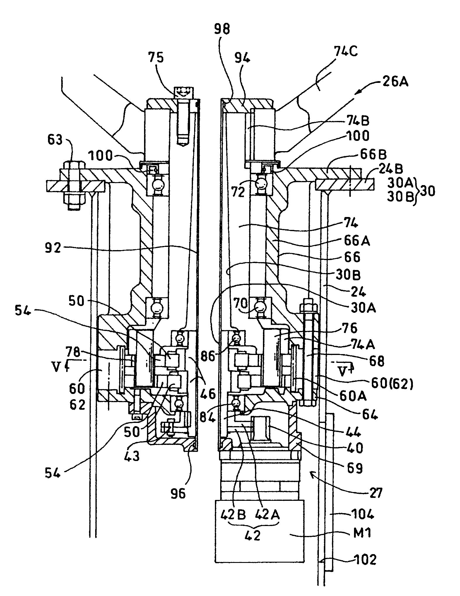
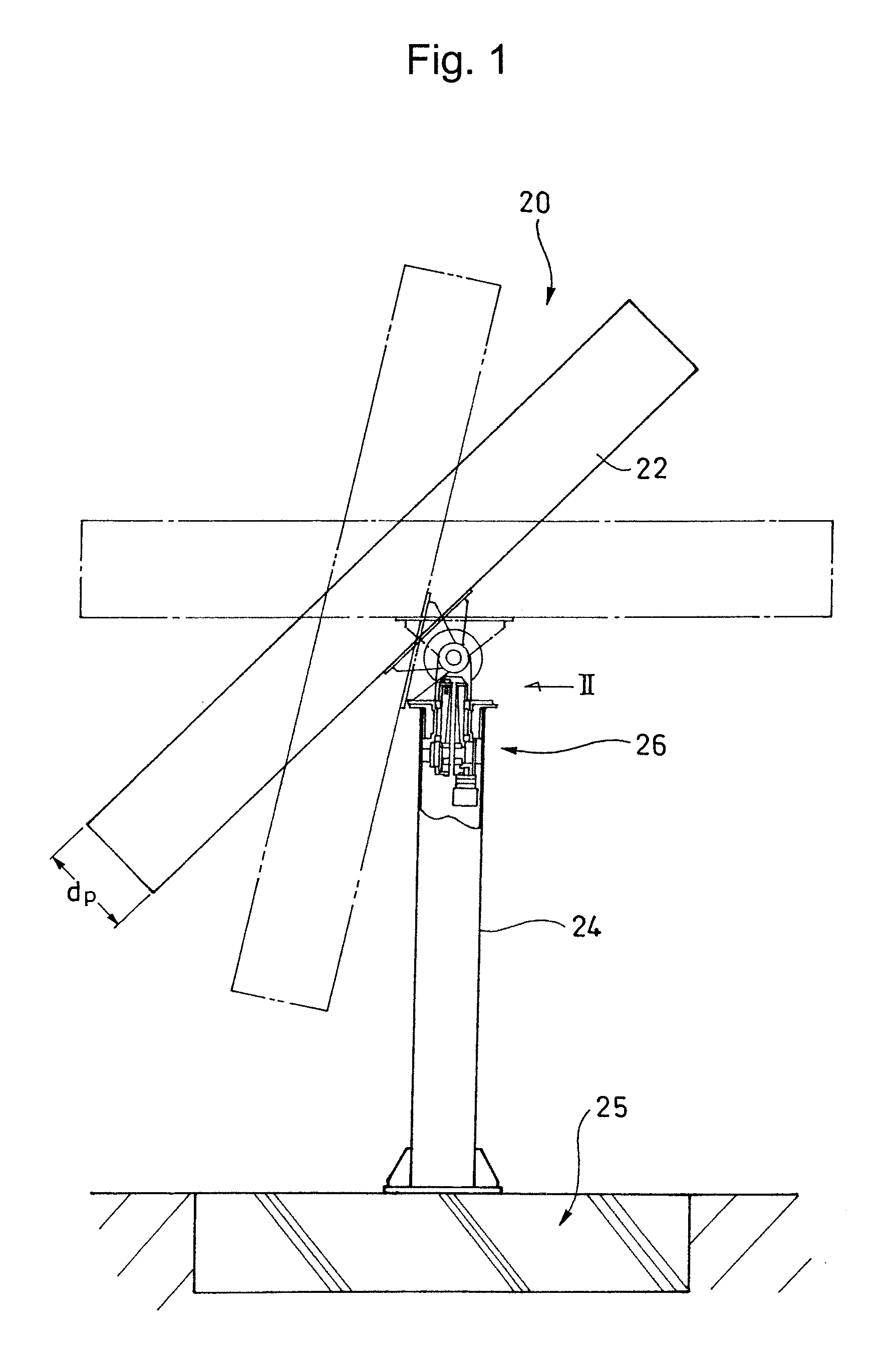
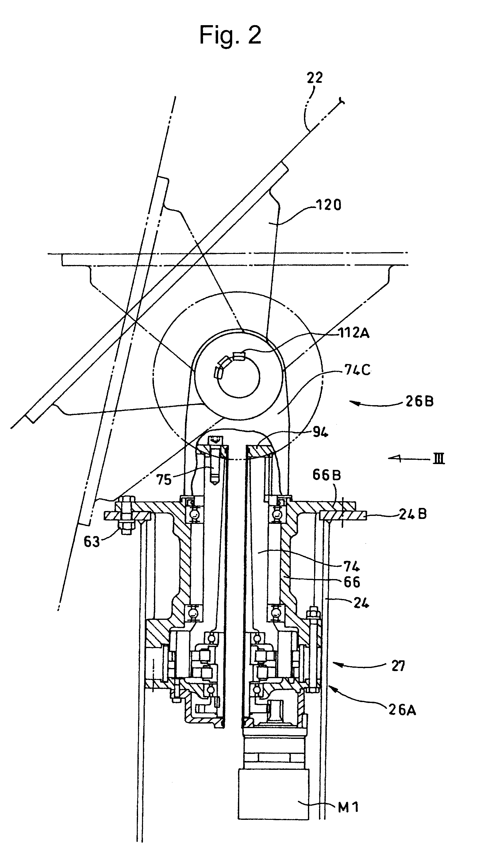
[0034]An example of a driving unit of a solar power generation system into which a reduction gear, related to an example of a power transmission device according to the invention, is assembled will be described below in detail. FIG. 1 shows the outline of the whole solar power generation system 20.

[0035]The solar power generation system 20 is provided with a power generation panel 22, and a cylindrical strut (support) 24 that supports the power generation panel 22 for drawing electric power from sunlight. The cylindrical strut 24 is erected on a foundation (base) 25 that is buried in the earth. A driving unit 26 for driving the power generation panel 22 is arranged and housed at an uppermost portion of the cylindrical strut 24.

[0036]In this embodiment, in order to enhance the efficiency of power generation to its highest level, a configuration in which sunlight is focused using a lens, not shown, while constantly tracking the sun's position, is increased to several hundreds times in...


PUM

PropertyMeasurementUnit
Temperatureaaaaaaaaaa
Deformation enthalpyaaaaaaaaaa

Abstract

The power transmission device has an internally meshing planetary gear mechanism that has an input shaft, an eccentric body provided on the input shaft, an externally toothed gear eccentrically oscillating via the eccentric body, and an internally toothed gear with which the externally toothed gear internally meshes. The externally toothed gear is assembled to the internally toothed gear in an interference fit.

Description

[0001]The contents of International Application No. PCT / JP200 8 / 051851, including specification, abstract and drawings, is incorporated herein by reference in its entirety.TECHNICAL FIELD[0002]The present invention relates to a power transmission device, and particularly, to a power transmission device provided with a reverse driving preventing function, and a method of producing the same.BACKGROUND ART[0003]Depending on its application, a power transmission device may require a reverse driving preventing function. In Patent Document 1, a configuration in which a speed reduction mechanism with a starting efficiency of 40% or more is adopted as a speed reduction mechanism of a drive system, and a frictional force imparting means that will always provide resistance during operation due to friction occurring between any rotational member on the power transmission path of the speed reduction mechanism, is arranged at any position on the power transmission path, is disclosed.[0004]This i...

Claims


Application Information

Patent Timeline
IPC IPC(8): F16H1/32B23P11/00
CPCF03D7/0204F05B2260/30F16H1/32Y10T29/49826Y02E10/722Y02E10/723F16H2001/325Y02E10/72
Inventor MINEGISHI, KIYOJIYANO, YUJI
Owner SUMITOMO HEAVY IND LTD
Learn More