
Leak-Off Control Agent

a technology of leakage control agent and filter cake, which is applied in the direction of sealing/packing, chemistry apparatus and processes, and wellbore/well accessories. it can solve the problems of affecting the production efficiency of filter cake, and affecting the formation of filter cak

Inactive Publication Date: 2010-01-07
SCHLUMBERGER TECH CORP
View PDF19 Cites 28 Cited by
  • Summary
  • Abstract
  • Description
  • Claims
  • Application Information

AI Technical Summary

Benefits of technology

[0004]One embodiment of the Invention is an oilfield treatment method that involves providing an oilfield treatment fluid that can form a filter cake on the face of a subterranean formation penetrated by a wellbore upon contacting the subterranean formation face at a pressure above the formation pressure. Plate-like particles are added to this fluid at a concentration less than that required to cover the formation face with a mon

Problems solved by technology

These fluids are injected into the formation at or above the pressure of formation fluids; this pressure difference between the treatment fluid and the reservoir fluid leads to invasion of the formation by the treatment fluid.
This filter cake can damage the formation and decrease productivity.
For example, in fracturing, the filter cake can decrease the conductivity of the fracture.
In addition, for VES based treatments, the fluid entering the formation can result in fracture face damage and reduced permeability.
Loss of fluid to the formation can also result in creation of water blocks, emulsions, clay swelling, and / or damage due to invading polymer, VES, additives, etc.
However the concentration of the polymer in the filter cake during leak-off cannot be controlled by adding traditional fluid loss additives; it is proportional to the concentration of the polymer in the fluid.
In addition, conventional fluid loss additives, and invading polymer, plug the pores of the formation due to their small size, and cause damage to permeability of the formation.

Method used


Image

  • Leak-Off Control Agent

Examples


example

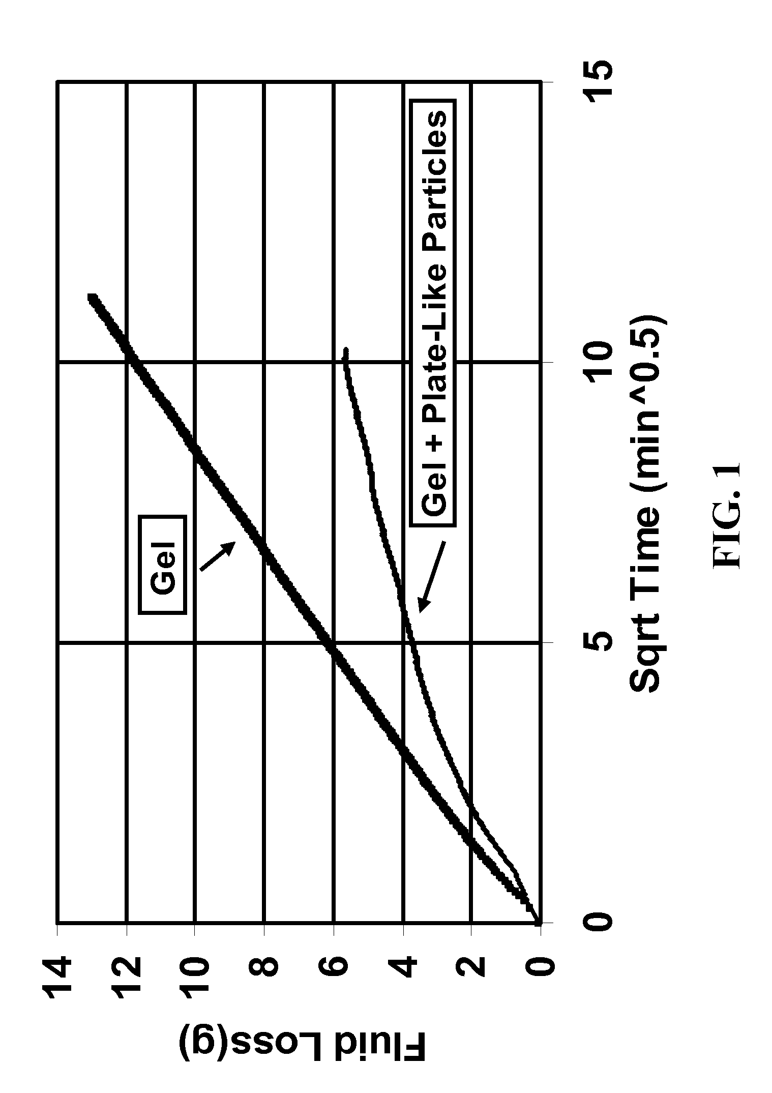
[0035]A static fluid loss test was performed in which a fracture fluid containing 3 kg / m3 (25 pounds per thousand gallons) of cross-linked guar gel was leaked through a 2.54 cm (1 inch) core by applying a differential pressure of 6.89 MPa (1000 psi). The same test was repeated with the addition of large plate-like particles to the cross-linked gel at a concentration of 3 kg / m3 (25 pounds per thousand gallons. The particles were about 0.5 by 0.5 mm, and were cut by hand from commercially available polyethylene film. Without the added particles, a thick, uniform filter cake was formed on the core surface. When the large plate-like particles were included in the fluid, the filter cake was very discontinuous; some regions of the core face were covered by the particles and had no polymer visible by eye, and the remainder of the core face was covered by polymer filter cake. FIG. 1 shows that fluid loss was substantially reduced by the addition of the large plate-like particles of the Inve...


PUM

PropertyMeasurementUnit
Lengthaaaaaaaaaa
Lengthaaaaaaaaaa
Concentrationaaaaaaaaaa

Abstract

A method of controlling leak-off and reducing the concentration of polymers (and / or other materials) in filter cakes formed when oilfield treatment fluids flow through subterranean formation faces involves adding large plate-like degradable and / or non-degradable, particles to polymer or VES-viscosified oilfield treatment fluids, at concentrations of such particles that are less than that required to cover the contacted formation face with a monolayer of such particles. When these large plate-like degradable and / or non-degradable particles are included in the fluid, polymer concentrates to form filter cake only in regions on the formation face (for example fracture faces) not shielded by the large plate-like particles, and the remaining formation face is not covered by concentrated polymer. As a result, the damage due to concentration of polymer and / or other materials in the filter cake during leak-off is reduced, and subsequent clean-up of the filter cake is easier.

Description

BACKGROUND OF THE INVENTION[0001]The Invention relates to filter cakes on the surfaces of subterranean formations. More particularly it relates to formation of filter cakes that are discontinuous and therefore less damaging and easier to clean up than conventional filter cakes. Most particularly it relates to inclusion in injected fluids of large plate-like particles, much larger than conventional fluid loss control additives, which create regions on the surfaces where leak off does not occur and filter cake does not form.[0002]Subterranean formations routinely come in contact with treatment fluids designed for drilling, fracturing, acidizing, acid fracturing, sand control, water control and other applications. These fluids are injected into the formation at or above the pressure of formation fluids; this pressure difference between the treatment fluid and the reservoir fluid leads to invasion of the formation by the treatment fluid. The treatment fluids (e.g. drilling muds, fractur...

Claims


Application Information

Patent Timeline
IPC IPC(8): C09K8/76
CPCC04B28/02C09K8/03C09K8/42C09K8/487C09K8/5045C09K8/70C09K8/508C09K8/5083C04B20/0008
Inventor PANGA, MOHAN K.R.ABAD, CARLOSSTILL, JOHN W.DROCHON, BRUNO
Owner SCHLUMBERGER TECH CORP
Learn More