Chronically-implantable active fixation medical electrical leads and related methods for non-fluoroscopic implantation

Inactive Publication Date: 2010-01-07
MEDTRONIC INC
View PDF3 Cites 77 Cited by
  • Summary
  • Abstract
  • Description
  • Claims
  • Application Information

AI Technical Summary

Benefits of technology

[0048]FIGS. 8A-D are elevational views schematically depicting a prior art (Medtronic model 5076) retractable helix lead and an embodiment according to the present invention. At least one aperture, or window, 9 is formed in a lateral portion of the proximal end portion of the lead adjacent to a part of the helix 10 (when retracted). A corresponding cover structure (e.g., a sleeve member) 7 couples to a base portion 5 of the h

Problems solved by technology

Since a retractable helix-type lead is often preferred for chronic therapy delivery, and such a lead is difficult if not impossible to image using the IsF system, the inventors discovered that for

Method used


Image

  • Chronically-implantable active fixation medical electrical leads and related methods for non-fluoroscopic implantation
  • Chronically-implantable active fixation medical electrical leads and related methods for non-fluoroscopic implantation
  • Chronically-implantable active fixation medical electrical leads and related methods for non-fluoroscopic implantation

Examples


Example

[0020]The following detailed description should be read with reference to the drawings, in which like elements in different drawings are numbered identically. The drawings depict selected embodiments and are not intended to limit the scope of the invention. It will be understood that embodiments shown in the drawings and described below are merely for illustrative purposes, and are not intended to limit the scope of the invention as defined in the claims.

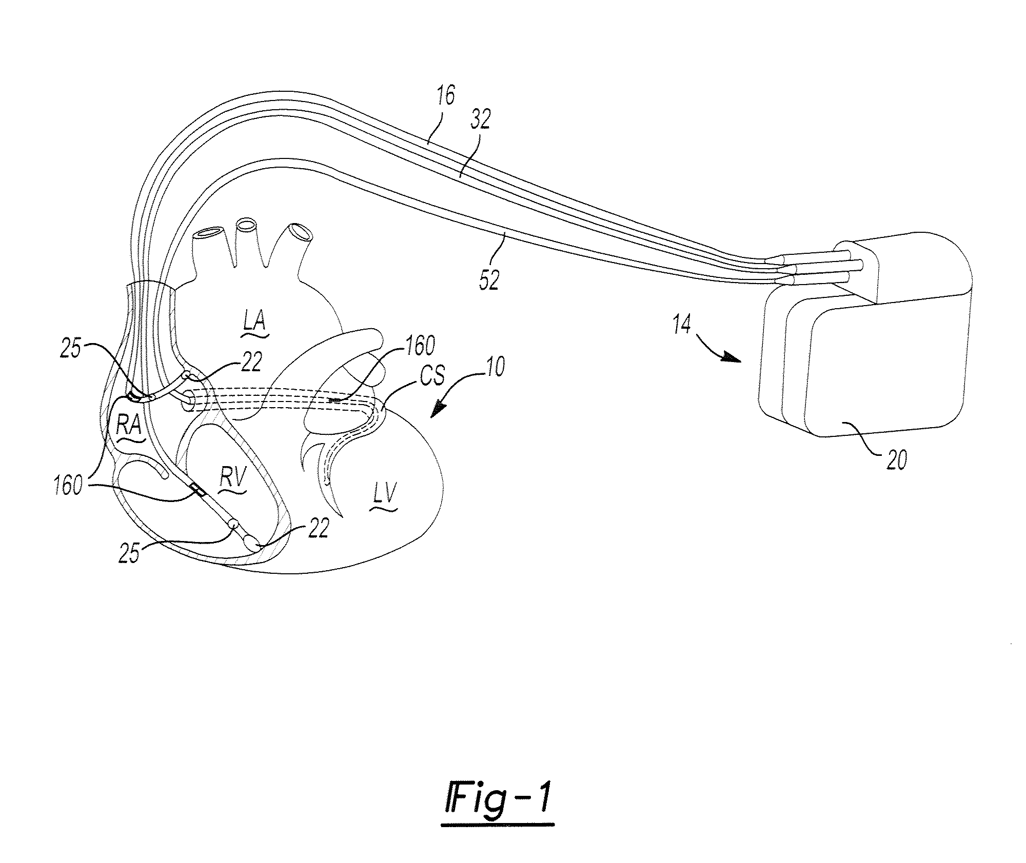
[0021]Certain embodiments of the invention may provide a non-invasive technique for monitoring the position, movement, and / or geometric characteristics of internal body tissue, such as cardiac muscle tissue. For example, such information may enhance the ability to assess certain parameters (e.g., parameters related to cardiac performance), and may also affect therapy delivery decisions. In one particular embodiment, for example, measuring the position and movement of leads appropriately placed in the heart for long-term therapy deli...


PUM


Abstract

Bio-impedance may be used for navigation systems to chronically implant pacing and defibrillation leads in the heart using anon-fluoroscopic position sensing unit (PSU), such as a modified LocaLisa® system from Medtronic Inc., which allows for variable frequency sampling of the position of electrode of a catheter. The PSU injects small AC signals via surface electrodes in three orthogonal axes, each on a slightly different frequency (e.g., near 30 KHz). Indwelling electrodes electrically connected to the PSU resolves the magnitude of induced voltage for each of the three frequencies, thus measuring voltage for each of the three axes. Voltages are divided by induced current to yield impedance in each axis for each electrode. Impedance is proportional to position within the body. Such a system requires that a conductive material, such as a retractable helical tip-electrode, be exposed during implantation. Since the tip is retracted during implantation, this disclosure provides a modified distal portion employing at least one aperture (or “window”) for fluid exposure of the helix-electrode and a deployable internal sleeve for covering the aperture(s) when the helix-electrode is extended.

Description

STATEMENT OF INCORPORATION BY REFERENCE[0001]This non-provisional U.S. patent application claims the benefit of the filing of the following provisional U.S. patent applications; namely: application Ser. Nos. 60 / 912,610; 60 / 882,420; 60 / 882,431; 60 / 882,435; 60 / 882,425; 60 / 882,428; 60 / 882,413 and each said application is hereby incorporated herein by reference in their respective entireties as if fully set forth herein.FIELD OF THE INVENTION[0002]The present invention relates generally to implantable medical devices (IMDs) and more particularly relates to electrical medical lead structures, systems and methods for collecting anatomical data of at least a portion of an anatomical organ or feature of interest using a non-fluoroscopically-based imaging system to thereby enable implantation of a chronically-implantable medical electrical lead (e.g., a cardiac pacing lead or the like).BACKGROUND OF THE INVENTION[0003]Prior art techniques relating to the instant invention include U.S. Pat. N...

Claims


Application Information

Patent Timeline
IPC IPC(8): A61N1/05
CPCA61N1/056A61N1/08A61N1/0573
Inventor MARKOWITZ, H. TOBYGIESE, CHADWALDHAUSER, STEVEN L.
Owner MEDTRONIC INC
Why Eureka
Try Eureka