Method of identification of cause of occurrence of springback, method of display of degree of effect of springback, method of identification of location of cause of occurrence of springback, method of identification of position of measure against springback, apparatuses of these, and programs of these

a technology of springback and occurrence, applied in the field of method of identification of cause of springback, method of identification of location of cause of springback, method of identification of position of measure against springback, etc., can solve the problems of nonlinear problem of numerical analysis of design tooling, difficult analysis, and increased work and cost in mechanical design stage of studying the method of forming formed members, so as to shorten the time for study and shorten the time for identification of location

Active Publication Date: 2010-01-14
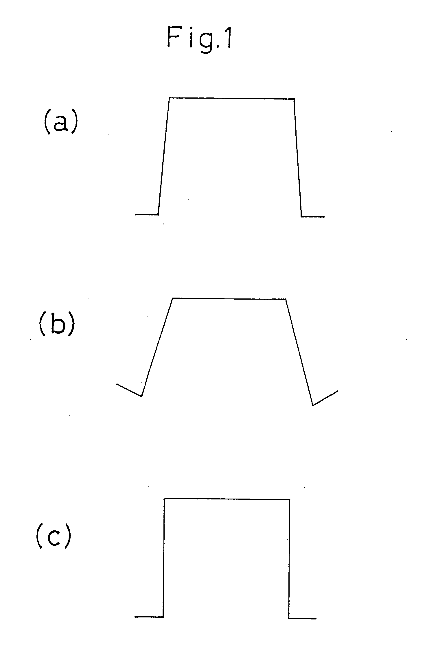
NIPPON STEEL CORP
View PDF71 Cites 40 Cited by
  • Summary
  • Abstract
  • Description
  • Claims
  • Application Information

AI Technical Summary

Benefits of technology

[0056]According to the present invention, by changing the identified location covered by analysis as the cause of occurrence of springback of a press formed product and numerically processing the physical property value/physical property quantity of that identified location and minimizing the springback value, there is provided a method which enables identification of the location of the cause of occurrence of springback and accurate derivation the physical property value/physical property quantity of the location of the cause, enables trial and error analysis to confirm the same, and economically and efficiently shortens the time for study of the method of forming a formed member.
[0057]Further, according to the present invention, by processing an identified location for analysis as the cause of occurrence of springback of a press formed product for at least one of the data of the physical property value and physical property quantity of each region dividing the press formed product and displaying by a contour diagram the springback value for each region based on the results of processing, there is provided a method which enables trial and error analysis on a computer, economically and efficiently shortens the identification of the location of the cause of occurrence of springback, and economically and efficiently shortens the time for study of the method of forming a formed product.
[0058]Furthermore, according to the present invention, by substituting a form and stress distribution different from the selected region for a selected region to be analyzed as the cause of occurrence of springback of the press formed product so as to minimize the springback value, there is provided a method which can identify the location of the cause of occurrence of springback and provide a measur

Problems solved by technology

Changes in conceptual design in the conceptual design stage cause changes in the formed members at the mechanical design stage, so the work and cost in the mechanical design stage of studying the method of forming the formed members become greater problems in the development process or development costs of automobiles etc.
However, designing tooling completely considering springback by numerical analysis is a nonlinear problem and extremely difficult, so the proposed method forms tooling simply considering springback by the finite element method.
Therefore, what measure becomes necessary when the allowable amount o

Method used


Image

  • Method of identification of cause of occurrence of springback, method of display of degree of effect of springback, method of identification of location of cause of occurrence of springback, method of identification of position of measure against springback, apparatuses of these, and programs of these
  • Method of identification of cause of occurrence of springback, method of display of degree of effect of springback, method of identification of location of cause of occurrence of springback, method of identification of position of measure against springback, apparatuses of these, and programs of these
  • Method of identification of cause of occurrence of springback, method of display of degree of effect of springback, method of identification of location of cause of occurrence of springback, method of identification of position of measure against springback, apparatuses of these, and programs of these

Examples


example 1

[0265]Examples will be used to explain the present invention in more detail.

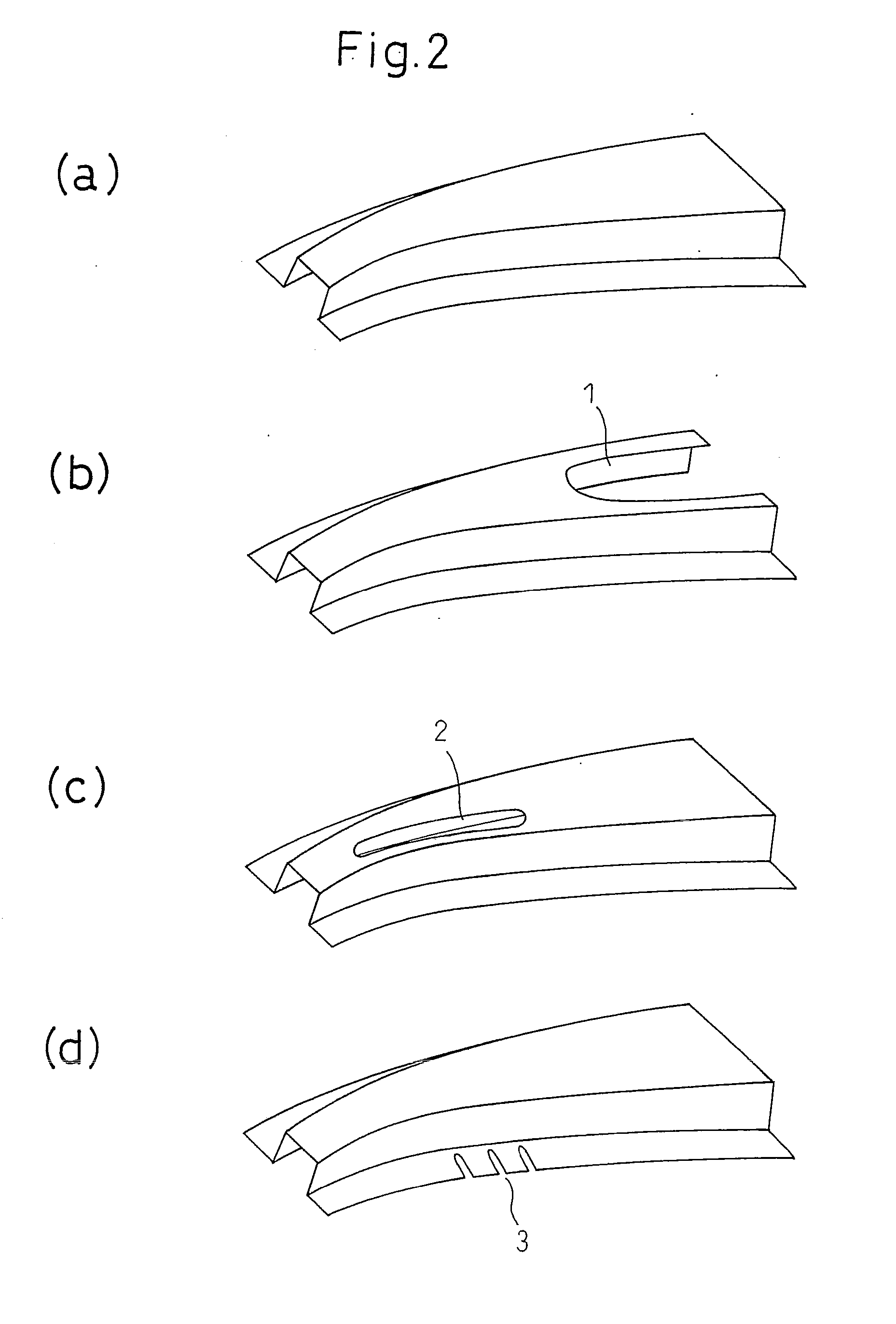
[0266]FIG. 19 gives views showing a part of a hat-formed cross-section covered by the springback analysis according to an embodiment of the present invention, wherein (a) is a perspective view and (b) is a cross-sectional view of the same. This is comprised of a web W0, side walls W1 and W2, and flanges F1 and F2.

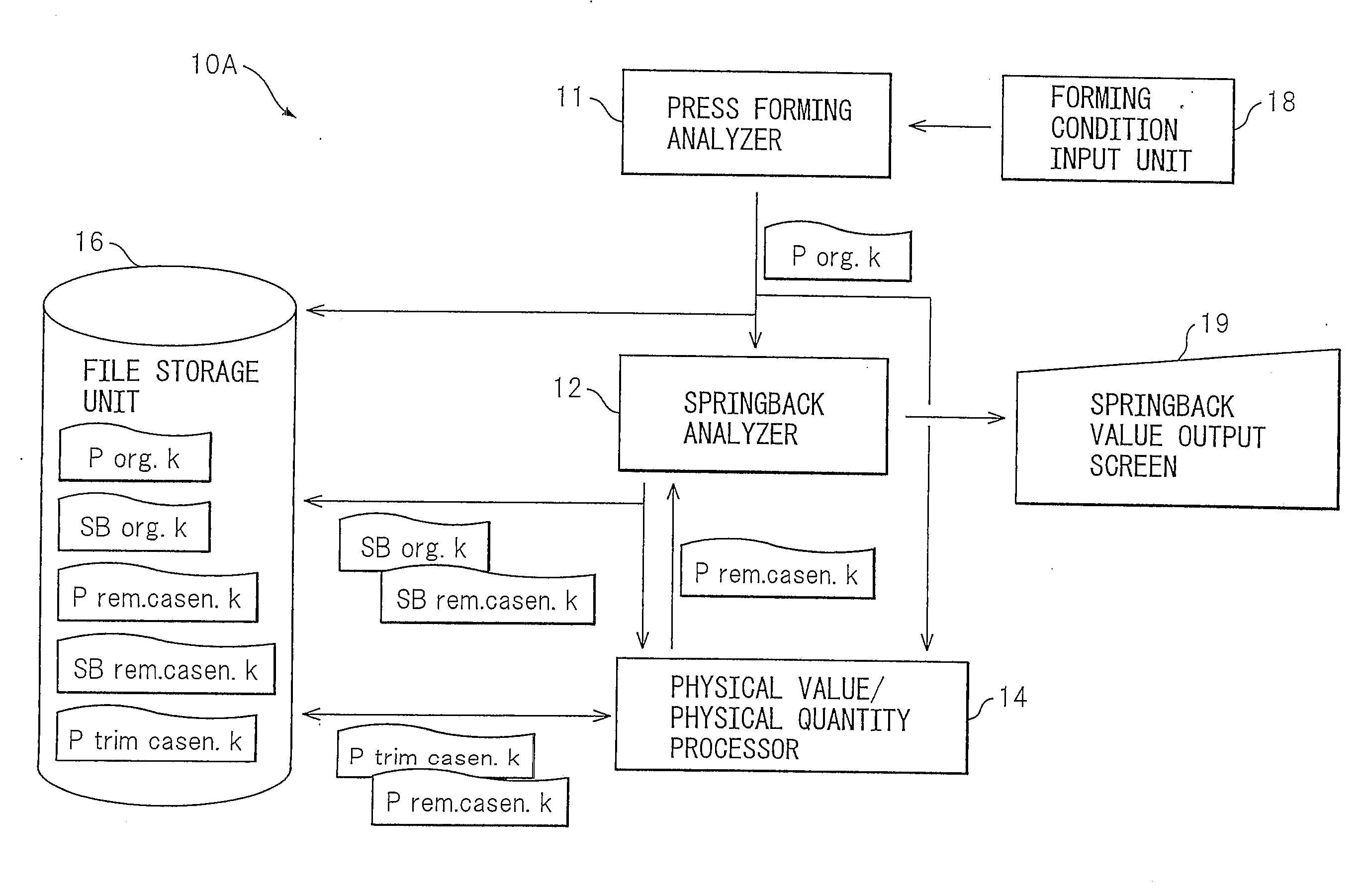
[0267]For the numerical analysis performed by the press forming analyzer 11 and springback analyzer 12, the existing plating forming simulation analysis software PAM-STAMP based on the finite element method was used. For the springback analysis, elastic analysis by the static implicit method was used.

[0268]The forming conditions used were data of high strength steel sheet having, as properties of the metal plate, a sheet thickness of 1.6 mm and a tensile strength of the 780 MPa class. Further, the form of the tooling (die, punch, holder) was modeled by shell elements and analyzed assuming a rigid bo...

example 2

[0295]FIG. 36 gives views showing a part of a hat-formed cross-section covered by springback analysis according to an embodiment of the present invention, wherein (a) is a perspective view and (b) is a cross-sectional view of the same. The hat formed cross-section is a symmetric left-right form. The width of the punch used was made 80 mm, the forming height was made 80 mm, and the width of the workpiece was made 100 mm.

[0296]For the numerical analysis performed by the press forming analyzer 11 and springback analyzer 12, the existing plate forming simulation analysis software PAM-STAMP based on the finite element method was used. For the springback analysis, elastic analysis based on the static implicit method was used.

[0297]The forming conditions used were data of high strength steel sheet having, as properties of the metal plate, a sheet thickness of 1.6 mm and a tensile strength of the 780 MPa class. Further, considering the hat cross-section symmetrical form, the analysis was co...

example 3

[0307]FIG. 39 gives views showing a part of a hat-formed cross-section covered by springback analysis according to an embodiment of the present invention, wherein (a) is a perspective view and (b) is a cross-sectional view of the same. This is comprised of a web W0, side walls W1, W2, and flanges F1, F2.

[0308]For the numerical analysis performed by the press forming analyzer 11 and springback analyzer 12, the existing plating forming simulation analysis software PAM-STAMP based on the finite element method was used. For the springback analysis, elastic analysis based on the static implicit method was used.

[0309]The forming conditions used were data of high strength steel sheet having, as properties of the metal plate, a sheet thickness of 1.6 mm and a tensile strength of the 780 MPa class. Further, the form of the tooling (die, punch, holder) was modeled by shell elements and analyzed assuming a rigid body. The clearance between the die and punch was made the same as the sheet thick...


PUM

PropertyMeasurementUnit
Lengthaaaaaaaaaa
Lengthaaaaaaaaaa
Lengthaaaaaaaaaa

Abstract

A method of identification of a cause of occurrence of springback comprising a press forming analysis step of numerically analyzing forming conditions of press forming to obtain forming data of a press formed part, a processing step of processing at least one of a physical property value and physical property quantity data of part of the regions of said press formed part among forming data of said press formed part, and a springback value calculation step of calculating a springback value based on the results of said processing.

Description

TECHNICAL FIELD[0001]The present invention relates to a method of identification of a cause of occurrence of springback occurring in a press formed product when press forming an automobile member etc. from steel sheet, steel bars, and other steel materials and also aluminum, magnesium, titanium, or other metals and a method of display of the degree of effect, a method of identification of the location of a cause of occurrence, and a method of identification of the position of a measure of the same, apparatuses of these, and programs of these.BACKGROUND ART[0002]Doors, bumpers, and numerous other automobile members, members for home electrical appliances, building materials, etc. are produced by press forming steel sheet. In recent years, demands have arisen for reducing the weight of these members. To meet these demands, high strength steel materials are being used to reduce the thickness of the steel materials etc.[0003]However, along with the higher strength of steel sheet, strict...

Claims


Application Information

Patent Timeline
IPC IPC(8): B21C51/00
CPCG06F2111/10G06F30/23B21D5/00Y02T10/82
Inventor YOSHIDA, TOHRUHAWATASHI, SHUNJIDAIMARU, SEIICHITANAKA, YASUHARUARIGA, TAKASHINIWA, TOSHIYUKIKURIYAMA, YUKIHISAOKAYAMA, SATORU
Owner NIPPON STEEL CORP
Why Eureka
Try Eureka