
MTJ based magnetic field sensor with ESD shunt trace

Active Publication Date: 2010-01-14
HEADWAY TECH INC
View PDF10 Cites 79 Cited by
  • Summary
  • Abstract
  • Description
  • Claims
  • Application Information

AI Technical Summary

Benefits of technology

[0018]A third object of the present invention is to provide a mechanism for ESD protection that both prevents static charge buildup and provides a safe path for charge dissipation.
[0019]A fourth object of the present invention is to provide an ESD-protected MTJ sensor that includes single domain, hysteresis-free MTJ cells to eliminate non-reproducibility of measurements.
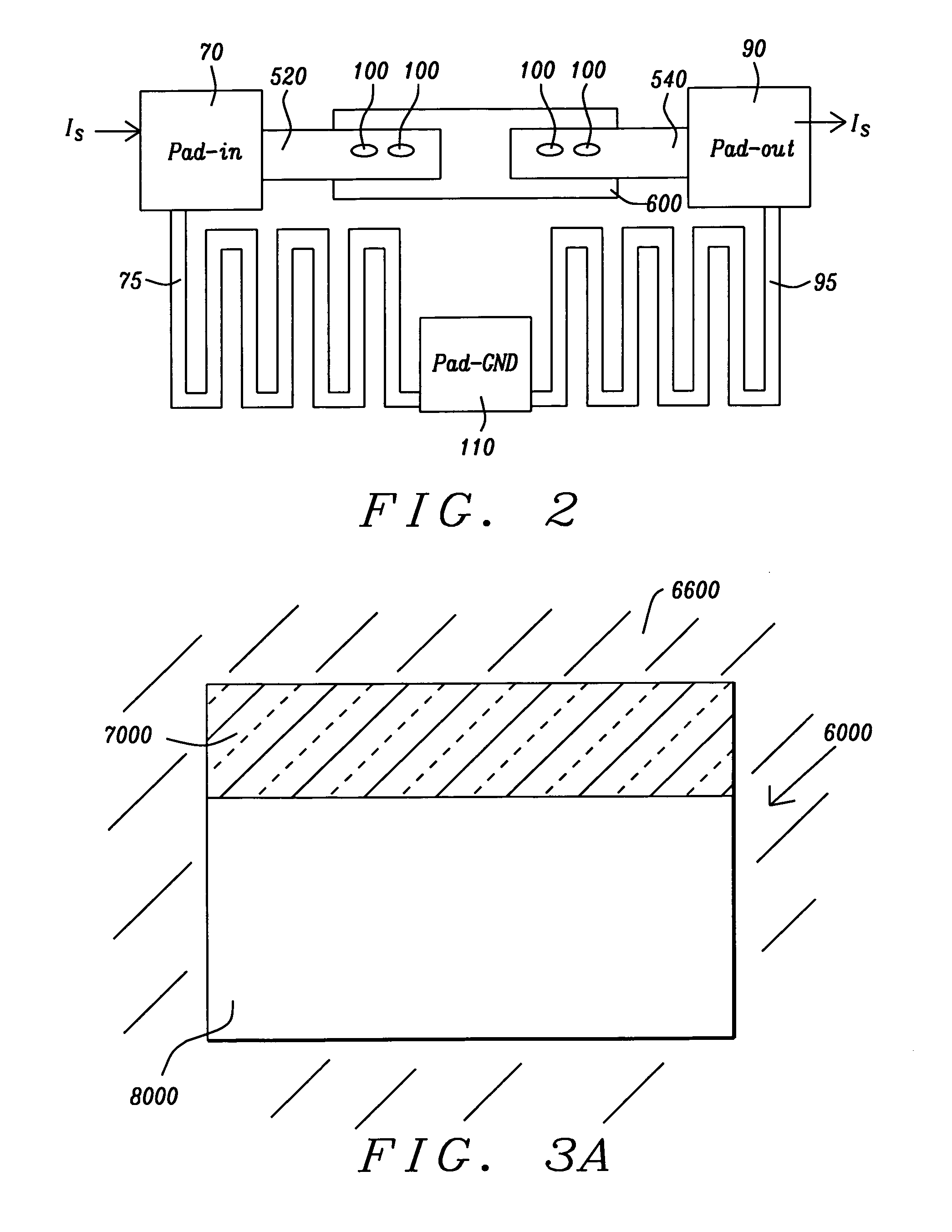
[0020]The objects of the present invention will be achieved by the use of an array of single domain MTJ sensors with domain restoration and resulting lack of hysteresis provided by a shape asymmetry and with ESD protection provided by conducting traces of relatively high resistance that serve to shunt electrostatic discharges away from the cells themselves and safely to ground.

Problems solved by technology

The MTJ junctions of MTJ cells normally have a very low breakdown voltage (less than 2 volts) and are highly susceptible to damage from electrostatic discharge (ESD) during handling, packaging and assembly.
When an MTJ cell is exposed to ESD, the junction may be totally or partially damaged and the sensing device of which it is a part will malfunction.

Method used


Image

  • MTJ based magnetic field sensor with ESD shunt trace
  • MTJ based magnetic field sensor with ESD shunt trace
  • MTJ based magnetic field sensor with ESD shunt trace

Examples


Embodiment Construction

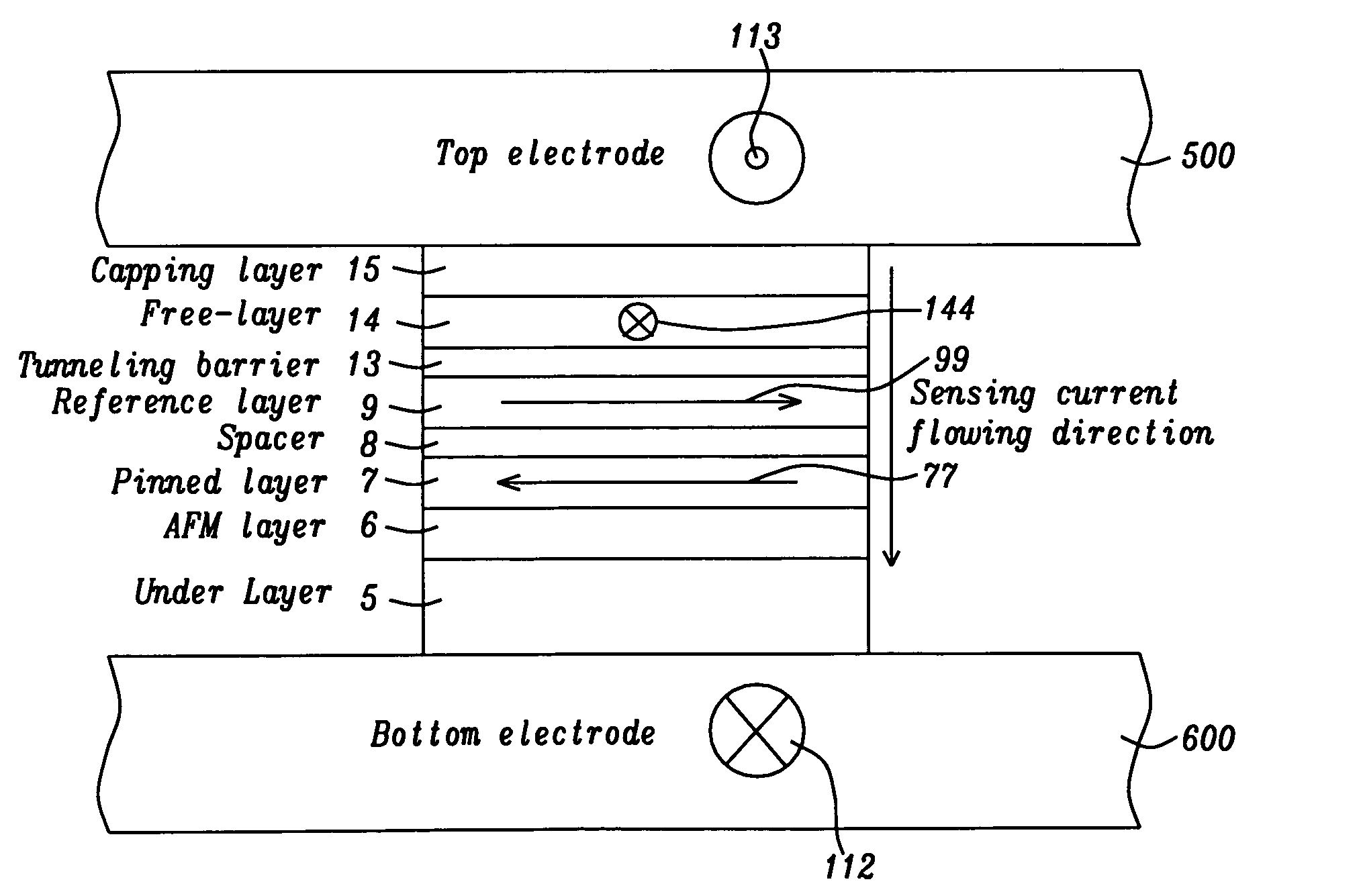
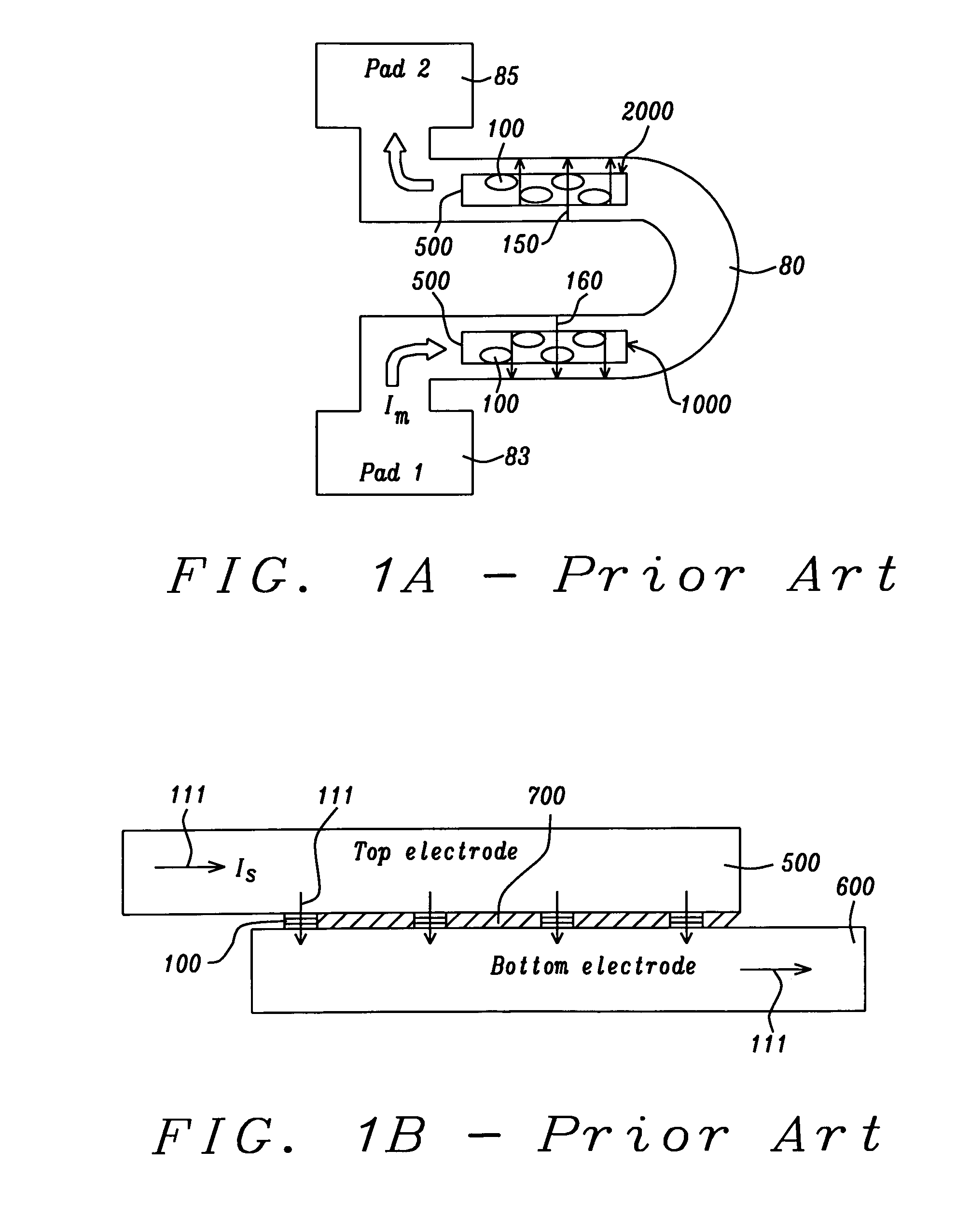
[0027]The preferred embodiment of the present invention is an ESD-protected current measuring device comprising two sensing structures placed at selected positions alongside a current carrying conductor. It is noted that the placement is preferably such that the sensing structures are physically in contact with the current carrying conductor, but not in electrical contact with it, e.g., separated from the conductor surface by a layer of insulating material. Each structure is formed as a plurality of electrically parallel MTJ cells that are themselves in parallel with a shunt trace that carries accumulated electrostatic charges harmlessly to ground, bypassing the MTJ cells. In a preferred configuration, the conductor is horseshoe-shaped and two sets of an equal number of MTJ cells, four being an exemplary number, are connected in parallel between upper and lower electrodes, and are placed on opposite sides of the horseshoe so that they experience current-produced magnetic fields that...


PUM

PropertyMeasurementUnit
Thicknessaaaaaaaaaa
Thicknessaaaaaaaaaa
Thicknessaaaaaaaaaa

Abstract

Presented herein is a shunted MTJ sensor formed of a plurality of electrically connected MTJ cells for measuring magnetic fields and currents and its method of fabrication. To provide stable single domain magnetic moments of the MTJ cells and to ensure that the magnetic moments return to a fixed bias point in the absence of external magnetic fields, the cells are formed of sufficiently small size and with elliptical cross-section of aspect ratio greater than 1.2. To eliminate the possibility of ESD damage to the cells, they are protected by a parallel shunt, formed as a trace of sufficiently high resistance that directs accumulated charges harmlessly to ground while bypassing the cells.

Description

RELATED PATENT APPLICATION[0001]This Application is related to Docket HMG06-046, Ser. No. 11 / 788,912, filed on Apr. 23, 07 and assigned to the same assignees as the present Application.BACKGROUND OF THE INVENTION[0002]1. Field of the Invention[0003]This invention relates to a magnetic field sensor using an MTJ junction cell. In particular, it relates to the use of such a magnetic field sensor also as a current sensor and to a method of protecting the sensor from electrostatic discharge (ESD) by means of a shunt.[0004]2. Description of the Related ArtBasic Operation of GMR and MTJ Cells[0005]Two types of small, multilayered magnetic devices that change their resistance in response to variations in an external magnetic field are presently in wide use in technologies such as read heads in hard disk drives and magnetic information storage devices or MRAM. These two device types are the GMR, or giant magnetoresistive device and the MTJ or magnetic tunneling junction device. The devices a...

Claims


Application Information

Patent Timeline
IPC IPC(8): G01R19/00G01R33/02G01R3/00
CPCG01R15/205Y10T29/49075G01R33/098
Inventor GUO, YIMINGORMAN, GRACE
Owner HEADWAY TECH INC
Learn More