Home gateway device

a technology for home gateways and gateway devices, applied in electrical appliances, digital transmission, data switching networks, etc., can solve the problems of increased operational complexity and manufacturing costs of home gateways, difficult to effectively isolate users, property loss and psychological harm to users, etc., to ensure the safety of a household interior network, reduce the complexity of controlling interior networking devices, and prevent access and control

Active Publication Date: 2010-01-14
CHINA MOBILE COMM GRP CO LTD
View PDF6 Cites 11 Cited by
  • Summary
  • Abstract
  • Description
  • Claims
  • Application Information

AI Technical Summary

Benefits of technology

[0005]In view of the many disadvantages of current home gateways, the aim of the present invention is to provide a home gateway device, in order to reduce the complexity of controlling interior networking devices, ensure the safety of a household interior network, prevent access and control from external illegal users, and differentiate between Internet signals and household appliance control signals, so as to avoid the probabilities of networking interruptions and control information errors.

Problems solved by technology

If there are a relatively greater number of devices in the household, this control scheme will increase the operational complexity and manufacturing cost of the home gateway.
Secondly, it is hard to effectively isolate information when Internet access signals of a computer and control signals of intelligent household appliances are both entering a home gateway, hence creating security risks such as illegal users outside a house using the Internet to control intelligent household appliances inside the house or to conduct destructive operations, thus causing property loss and psychological harm to the user.
Finally, when control signals of an interior intelligent appliance are entering a home gateway, the home gateway may not be able to effectively distinguish between Internet access signals and household appliance control signals, thus causing Internet access interruption or errors in control information.

Method used


Image

  • Home gateway device
  • Home gateway device
  • Home gateway device

Examples


embodiment 1

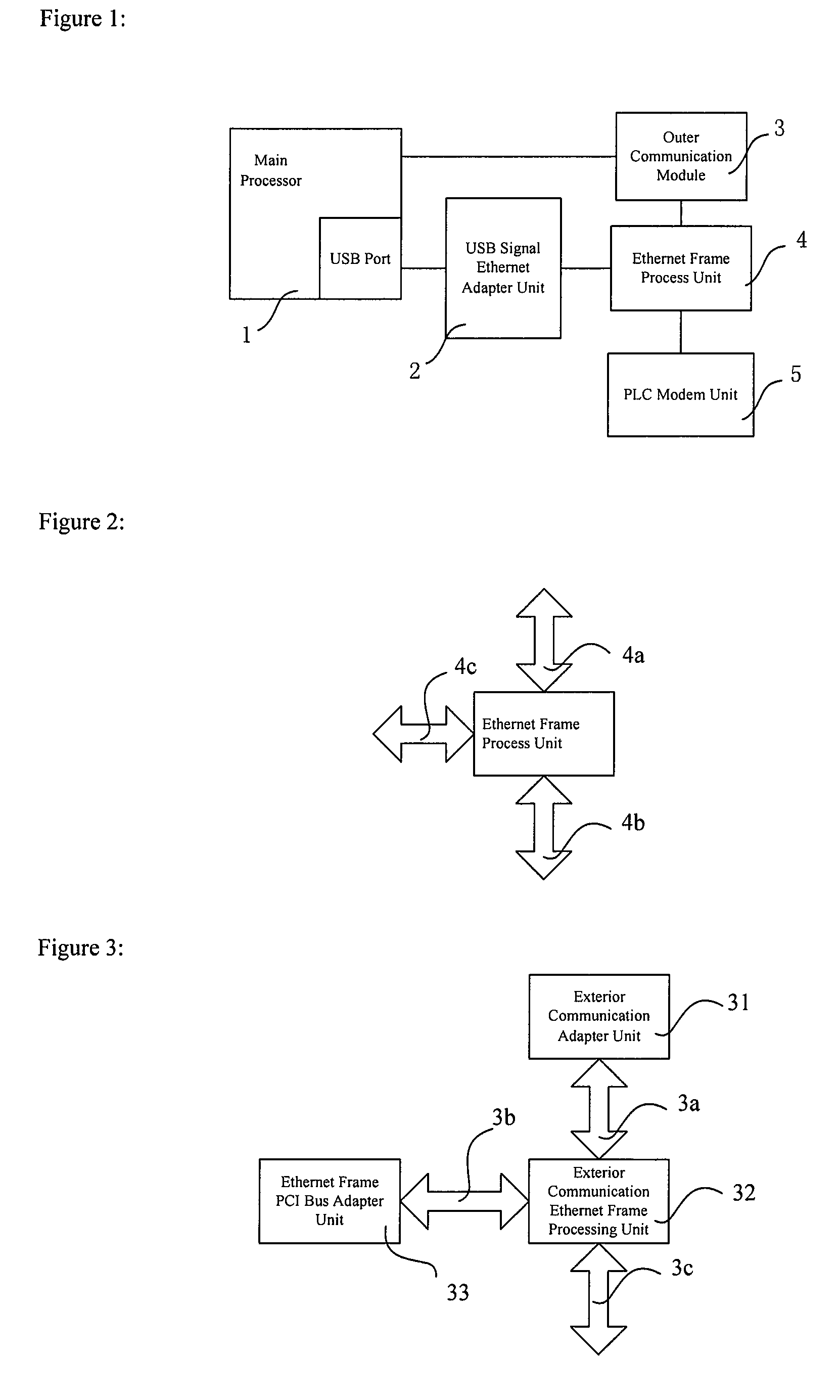
[0058]As shown in FIG. 1, a schematic illustration showing the structure of a home gateway device provided by Embodiment 1 of the present invention, the home gateway device comprises: a main processor 1, a USB signal Ethernet adapter unit 2, an outer communication module 3, an Ethernet frame process unit 4, and a power line communication (PLC) modulation and demodulation (modem) unit 5. The main processor 1 is used for generating information process signals and control signals; the main processor 1 has USB ports and is connected to other modules of the home gateway device by a USB bus. The USB signal Ethernet adapter unit 2 is connected to a USB port of the main processor 1, and is used for signal translation between USB signals and Ethernet signals. For household information appliances inside a house, a main control computer is a host device, while the household information appliances inside the house are USB based exterior computer devices of the host device. The above host device...

embodiment 2

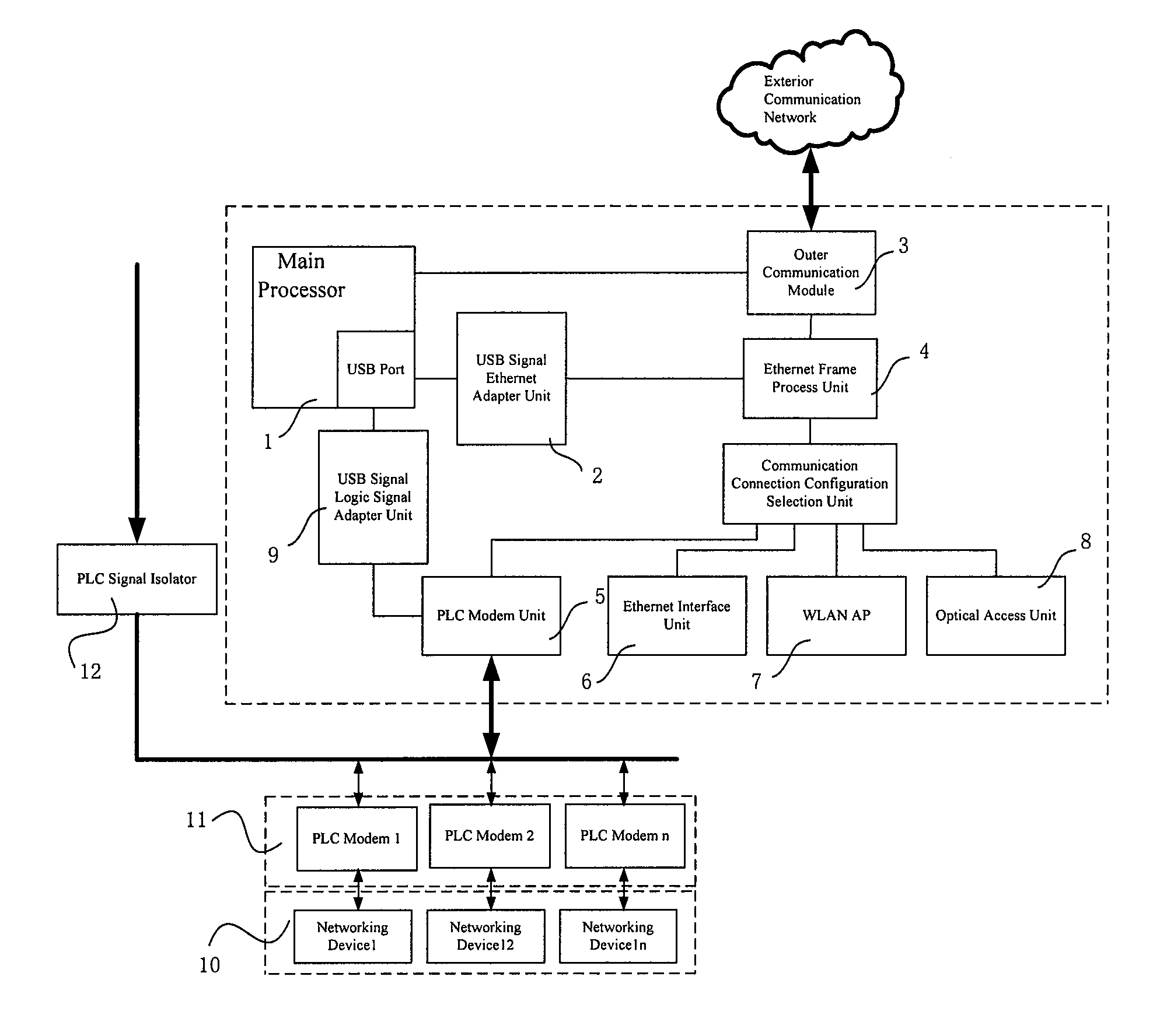
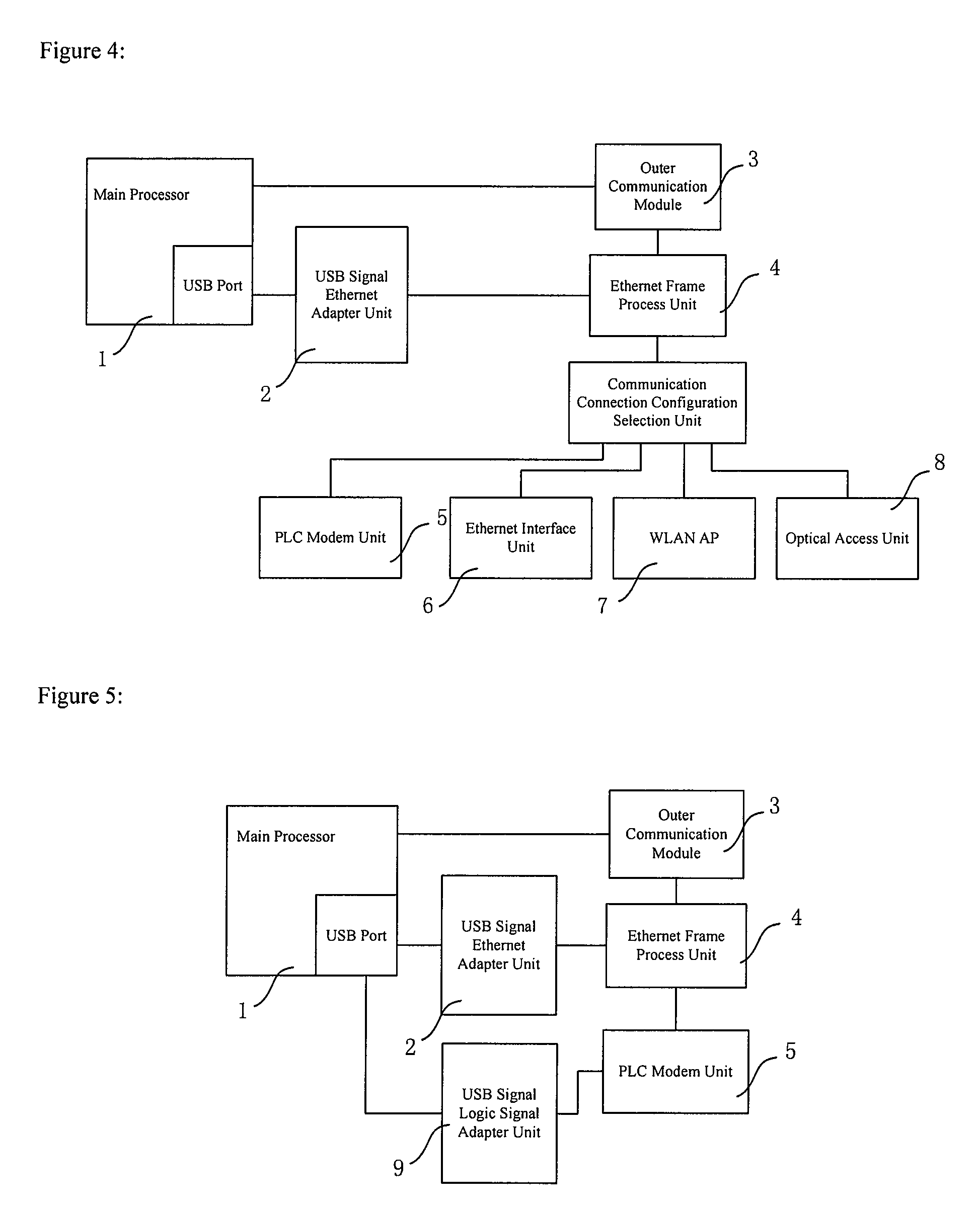
[0092]FIG. 4 is a schematic illustration showing the structure of a home gateway device provided by Embodiment 2 of the present invention. Different from Embodiment 1, an inner interface unit comprising: a PLC modem unit 5, an Ethernet interface unit 6, a WLAN AP 7 and an optical access unit 8. A communication connection configuration selection unit is set in between an Ethernet frame process unit 4 and the inner interface unit. The communication connection configuration selection unit is connected to the Ethernet frame process unit 4, the PLC modem unit 5, the Ethernet interface unit 6, WLAN AP 7, and the optical access unit 8, respectively. The Ethernet interface unit is used for connecting networking devices in an interior network through an Ethernet. The wireless LAN access point WLAN AP 7 is used for communication with networking devices in an interior network through wireless connection. The optical access unit is used for performing optical-to-electric transformation on optic...

embodiment 3

[0097]FIG. 5 is a schematic illustration showing the structure of a home gateway device provided by Embodiment 3 of the present invention. Embodiment 3 added a USB signal logic signal adapter unit 9 to Embodiment 1. The USB signal logic signal adapter unit 9 is connected to a main processor 1 and a PLC modem unit 5, for transforming USB signals to serial logic control signals. Since apart from those household information appliances, there are simple appliances that only have a few logic functions, such as an electric lamp, an electric controlled faucet, etc. For these appliances, it is only necessary to send a few logic control commands for on / off switching, without any complicate information interchange. The USB signal logic signal adapter unit transforms USB control signals sent by the main processor to serial logic control signals, and modulates these logic control signals into power line carrier signals using the PLC modem unit 5, so that household appliances may be controlled t...


PUM


Abstract

The present invention relates to a home gateway device. The home gateway device comprises a main processor to generate information process signals and control signals, a computer bus signal Ethernet adapter unit connected to the main processor to translate the signals between computer bus signals and Ethernet signals, an Ethernet frame process unit connected to the computer bus signal Ethernet adapter unit to forward the received Ethernet frame based on a prearranged policy, an inner interface unit connected to the Ethernet frame process unit to connect interior networking devices, and an outer communication module connected to the main processor and the Ethernet frame process unit. The centralized control of the home gateway device of the present invention can decrease the requirement that the household appliances should be intellectualized, thereby achieving more flexible control and reducing the cost. The uplink and downlink Ethernet signals are controlled by using the prearranged policy to separate the Ethernet signals for Internet access from the Ethernet signals of the household information appliances, and avoid the threat due to the unsafe factors.

Description

FIELD OF THE INVENTION[0001]The present invention relates to a home gateway device. In particular, the present invention relates to a home gateway device which separates the Internet channel from the household information appliances control channel by distinguishing external signals from internal access signals.BACKGROUND OF THE INVENTION[0002]With the arrival of the “information age” and the popularization of computer networks, intellectualizing and networking inside households are gradually becoming realities. Presently there are various researches on the subject of an intelligent household network. Most of these researches are based on existing computer network technologies, where different household appliances and devices are connected into a network to provide a diversity of services that are convenient, comfortable, safe and efficient to use through the network. An important subject of these researches is how to implement information exchange between the exterior and interior ...

Claims


Application Information

Patent Timeline
Patent Type & Authority Applications(United States)
IPC IPC(8): H04L12/56H04L12/46H04L12/66H04L12/70
CPCH04L29/12839H04L61/2514H04L61/2596H04L29/12584H04L12/66H04L29/12367H04L61/6022H04L2101/622H04W88/16
Inventor LI, HANZHANG, YANLIU, JINGLEIOUYANG, CONGXINGWEI, BINGHUANG, YUHONG
Owner CHINA MOBILE COMM GRP CO LTD
Why Eureka
Try Eureka