Biometrics authentication device and portable terminal

a biometric authentication and portable terminal technology, applied in the field of biometric authentication devices, can solve the problems of lowering the contrast-to-noise ratio, insufficient light intensity, unstable intensity of light distribution in the picked up image, etc., and achieve the effect of enhancing the authentication accuracy of the biometric authentication devi

Active Publication Date: 2010-01-14
HITACHI LTD
View PDF2 Cites 107 Cited by
  • Summary
  • Abstract
  • Description
  • Claims
  • Application Information

AI Technical Summary

Benefits of technology

[0018]According to the representative mode of this invention, the biometric authentication device can be enhanced in authentication accuracy.

Problems solved by technology

Firstly, in blood vessel authentication devices where infrared light is used as irradiation light, the backlight of a liquid crystal display cannot be used as the irradiation light source. Blood vessel authentication device therefore need to include a separate infrared light source on the periphery of the liquid crystal display. Then, the problem of insufficient intensity of light arises in a central part of the liquid crystal display which is distant from the infrared light source.
Secondly, in blood vessel authentication devices, the relative positional relation between the light source and a subject is easily changed depending on where the subject is placed. This leads to the problem of unstable intensity of light distribution in a picked up image.
Further, even if a liquid crystal backlight is somehow made usable as the irradiation light source, blood vessel authentication devices undesirably allow scattered light that is generated when irradiation light is transmitted through the substrate of the translucent sensor to intrude in a picked up image.
The quantum noise of scattered light causes lowering in contrast-to-noise ratio of a picked up image and accordingly degrades the image quality of the picked up image.

Method used


Image

  • Biometrics authentication device and portable terminal
  • Biometrics authentication device and portable terminal
  • Biometrics authentication device and portable terminal

Examples


first embodiment

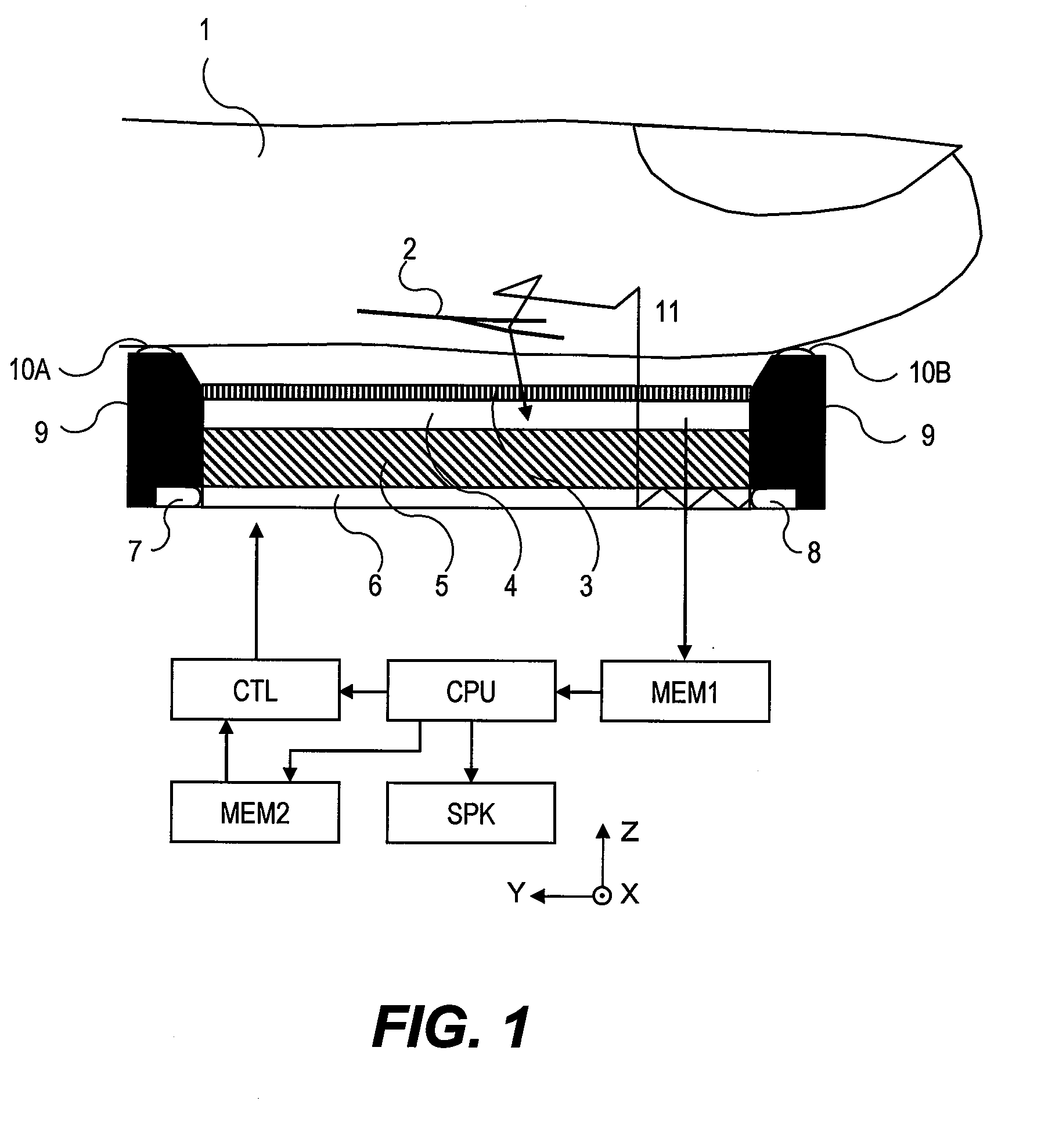
[0045]FIG. 1 is a structural diagram of a biometric authentication device according to a first embodiment of this invention.

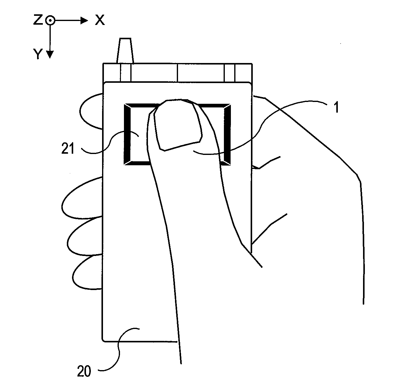
[0046]The biometric authentication device performs authentication based on the pattern of blood vessels 2 of a subject 1. The subject 1 is a human finger in this embodiment, but may be other body parts than a finger as long as the pattern of the blood vessels 2 can be photographed. Examples of other body parts than a finger include the palm of a hand and the back of a hand.

[0047]In this embodiment, the width direction of the subject 1 is an X axis, the longitudinal direction of the subject 1 is a Y axis, and a direction perpendicular to an input face of the biometric authentication device is a Z axis.

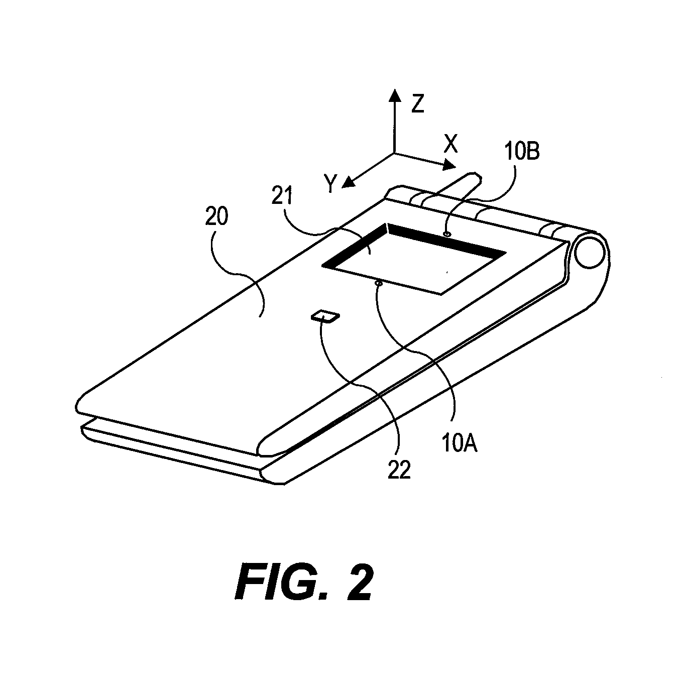
[0048]The biometric authentication device includes a grid 3, a sensor board 4, a liquid crystal display board 5, an optical waveguide 6, a display light emission diode (LED) 7, a detection LED 8, a support frame 9, electrodes 10A and 10B, a shooting control device ...

second embodiment

[0184]The biometric authentication device 21 of a second embodiment of this invention executes biometric authentication based on images that are obtained by performing actual shooting twice.

[0185]The biometric authentication device 21 of the second embodiment has the same structure as the biometric authentication device structure (FIG. 1) of the first embodiment. A detailed description on the structure is therefore omitted here. Authentication processing that is executed by the biometric authentication device 21 of the second embodiment is the same as the authentication processing (FIG. 7) executed by the biometric authentication device 21 of the first embodiment, except Steps S8 and S9. Descriptions on the same processing steps are therefore omitted here.

[0186]FIG. 18 is an explanatory diagram of a actual shooting mask image A, which is displayed on the biometric authentication device 21 in first-time actual shooting according to the second embodiment of this invention. FIG. 19 is ...

third embodiment

[0223]The biometric authentication device 21 of a third embodiment of this invention uses a transmissive mask image in actual shooting.

[0224]The biometric authentication device 21 of the third embodiment has the same structure as the biometric authentication device structure (FIG. 1) of the first embodiment. A detailed description on the structure is therefore omitted here. Authentication processing that is executed by the biometric authentication device 21 of the third embodiment is the same as the authentication processing (FIG. 7) executed by the biometric authentication device 21 of the first embodiment, except Steps S7 and S8. Descriptions on the same processing steps are therefore omitted here.

[0225]FIG. 23 is an explanatory diagram of a transmissive mask image 230, which is displayed on the biometric authentication device 21 when the subject 1 is photographed according to the third embodiment of this invention.

[0226]All regions in the transmissive mask image 230 are transluce...


PUM


Abstract

Provided is a biometric authentication device for identifying an individual based on a biometric pattern of the subject included in a picked up image, comprising: a light guiding unit for outputting light from a surface thereof; a liquid crystal display (LCD) unit for adjusting, on a display pixel basis, an intensity of light output from the surface of the light guiding unit; an image pickup unit for picking up an image of the subject; a display light source for emitting light used as a backlight of the LCD unit; a detection light source for emitting light for irradiating the subject; and a control unit for controlling processing of the biometric authentication device The control unit turns on the detection light when the image pickup unit picks up a first image, which is used for authentication, and turns on the display light source when the LCD unit displays information.

Description

TECHNICAL FIELD[0001]This invention relates to a biometric authentication device which utilizes features of biometric information to identify individuals, and more particularly, to a technology of identifying an individual based on a blood vessel pattern.BACKGROUND ART[0002]Biometric authentication in which features of biometric information are used to identify individuals has lately been attracting attention. Examples of biometric information include fingerprints, iris or blood vessel patterns.[0003]Advantages of biometric authentication are convenience and high security, which are owing to the fact that biometric authentication does not require a person to carry a key with him / her and has less fear of fraudulent acts as a consequence of the loss or theft of the key, or the like.[0004]Of varying types of biometric authentication, authentication using blood vessel patterns (blood vessel authentication) is becoming popular. Blood vessel patterns which are information within a living ...

Claims


Application Information

Patent Timeline
Patent Type & Authority Applications(United States)
IPC IPC(8): G06K9/00H04M1/00
CPCG06K9/00033G06K2009/00932G06K9/00885G06V40/1312G06V40/10G06V40/14
Inventor UEKI, HIRONORIKONNO, YASUTAKA
Owner HITACHI LTD
Why Eureka
Try Eureka