Image forming apparatus

Inactive Publication Date: 2010-01-14
RICOH KK
View PDF5 Cites 31 Cited by
  • Summary
  • Abstract
  • Description
  • Claims
  • Application Information

AI Technical Summary

Benefits of technology

[0009]It is a general object of the present invention to provide a novel and useful ima

Problems solved by technology

Particularly in the developing unit, increases in the speed at which a developing process is performed have led to increases in the amount of frictional heat produced by the stirring of a toner and a carrier for imparting an electric charge to the toner, where the temperature of the toner increases as high as its softening point.
Sine the resultant molten toner may coagulate and cause a developing defect, the toner needs to be maintained at temperature

Method used


Image

  • Image forming apparatus
  • Image forming apparatus
  • Image forming apparatus

Examples


embodiment 1

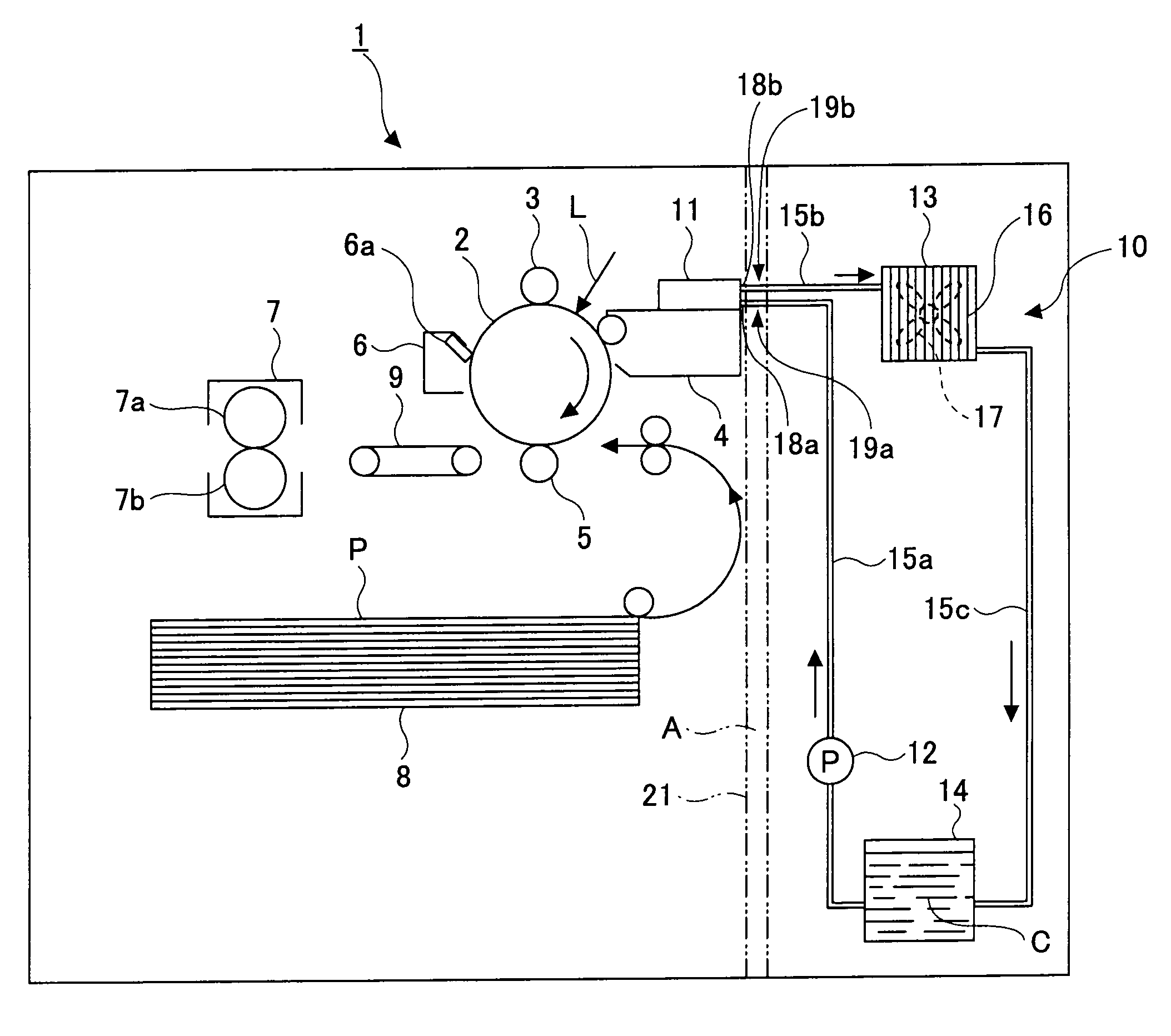
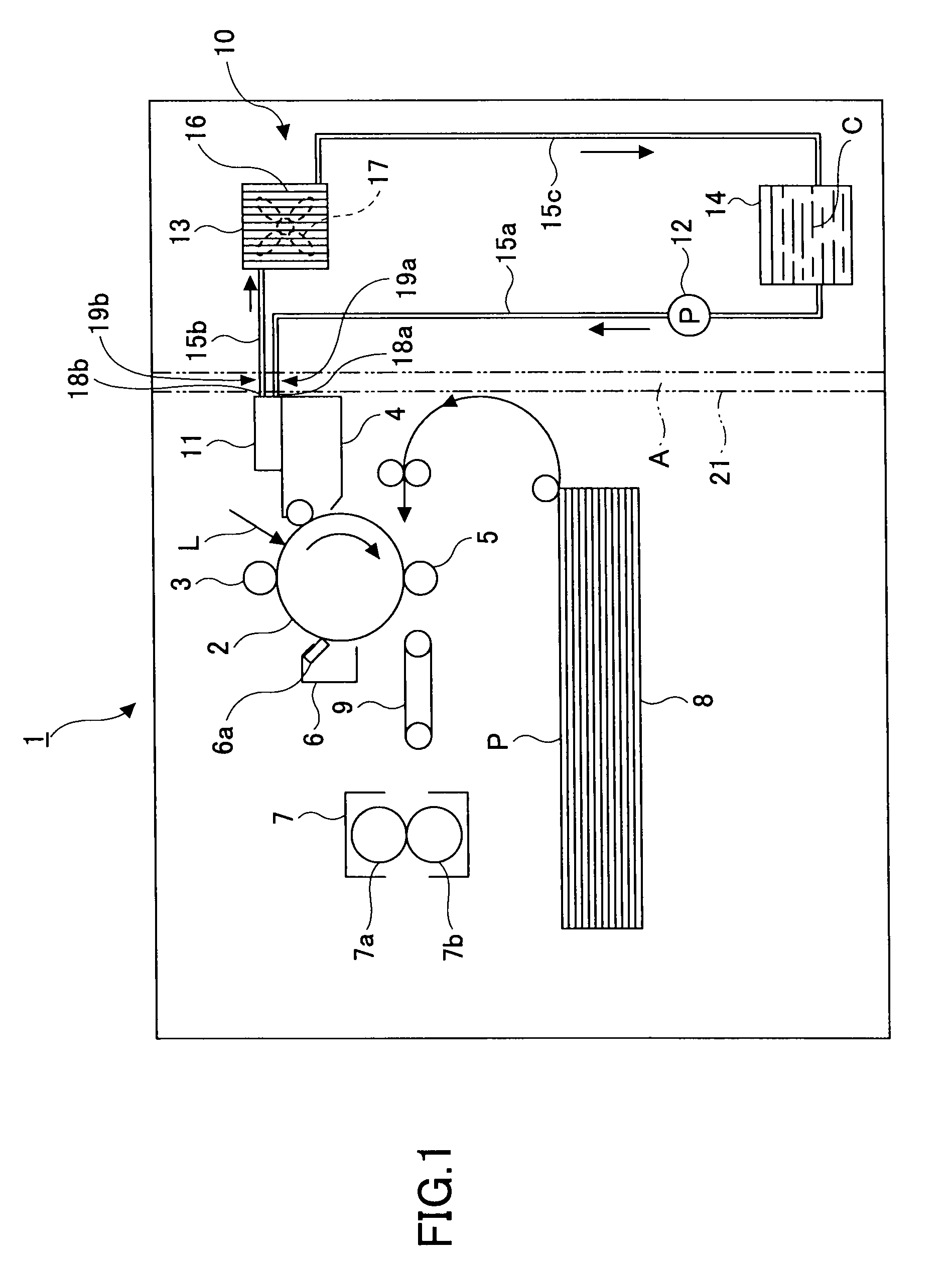
[0026]FIG. 1 shows an image forming apparatus 1 based on electrophotography equipped with a liquid-cooled cooling system according to Embodiment 1 of the present invention. The image forming apparatus 1 is a high-speed machine capable of performing an image forming process (such as printing) at the rate of 100 to 120 A4-sized sheets per minute, for example, where a recording medium such as sheets of paper may be fed continuously for a long time (such as for days).

[0027]As shown in FIG. 1, the image forming apparatus (which may be a printer) 1, which is configured to output a black-and-white image, includes a photosensitive drum 2 around which a charging roller 3, a developing unit 4, a transfer roller 5, and a cleaning unit 6 are disposed. A fusing unit 7 is disposed downstream of the transfer roller 5 in a direction of transport of a recording sheet P. The developing unit 4 is in thermal contact with a heat-receiving member 11 of a liquid-cooled cooling system 10. The details of th...

embodiment 2

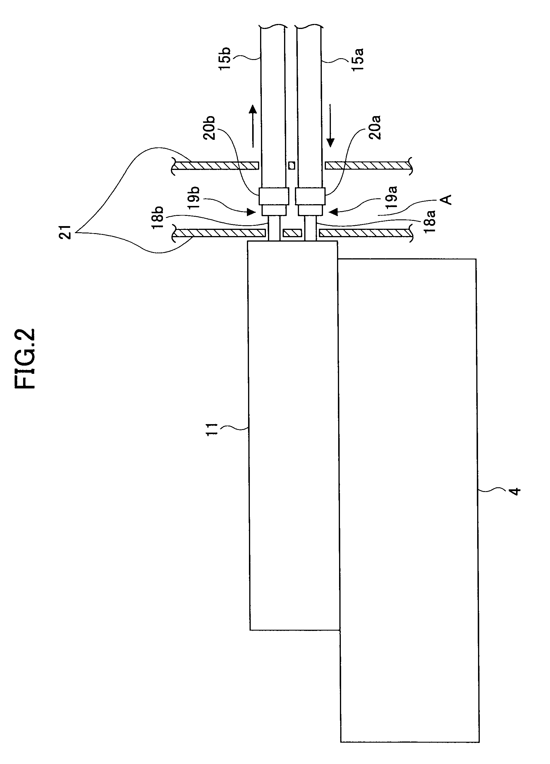
[0042]In accordance with Embodiment 2, as shown in FIG. 4, the inlet-side pipes 18a and 18b on the side of the heat-receiving member 11 are bent substantially 90° downward at intermediate portions thereof, so that the joint portions 19a and 19b are vertically disposed in the space A enclosed by the shielding members 21, as opposed to Embodiment 1 in which the joint portions 19a and 19b are disposed horizontally. Embodiment 2 is similar to Embodiment 1 as shown in FIGS. 1 through 3 in other respects, and thus the description of the similar elements or functions is omitted.

embodiment 3

[0043]In accordance with Embodiment 3, as shown in FIG. 5, the inlet-side pipes 18a and 18b on the side of the heat-receiving member 11 are bent upward by approximately 90° at intermediate portions thereof, so that the joint portions 19a and 19b are vertically disposed in the space A enclosed by the shielding members 21. Embodiment 3 is similar to Embodiment 1 as shown in FIGS. 1 through 3 in other respects, and therefore the description of the similar elements or functions is omitted. In this embodiment, too, the image forming portion 22 and the electrical component drive portion 23 can be prevented from being immersed in the coolant should it leak via the joint portion 19a or 19b due to the aging of the apparatus, for example, as in Embodiment 1.


PUM


Abstract

An image forming apparatus having a liquid-cooled cooling system prevents problems caused by a potential leakage of coolant used in the liquid-cooled cooling system. The liquid-cooled cooling system cools a heat-generating image forming portion using the coolant, which is circulated by a pump through a circulating path. The cooling system includes a heat-receiving member disposed in thermal contact with the image forming portion to absorb heat generated by the image forming portion. The heat-receiving member is connected with the circulating path via a joint. The joint is disposed within an enclosed space between the image forming portion and an electrical component drive portion for driving or controlling the image forming portion, so that the image forming portion and the electrical component drive portion can be protected from the coolant in the event of coolant leakage via the joint.

Description

BACKGROUND OF THE INVENTION[0001]1. Field of the Invention[0002]The present invention generally relates to image forming apparatuses for forming an image based on electrophotography, such as copy machines and printers. In particular, the invention relates to an image forming apparatus equipped with a liquid-cooled cooling system for cooling heat-generating units of the apparatus, such as a developing unit.[0003]2. Description of the Related Art[0004]Electrophotographic image forming apparatuses, such as copy machines, printers, facsimiles, and multifunction peripherals, contain various units that generate heat during an image forming operation, such as a write unit and a developing unit. These units may be cooled by an air-cooled system using a cooling fan. However, the amount of heat generated by these units in an image forming apparatuses has increased as a result of increases in image formation processing speed. Particularly in the developing unit, increases in the speed at which...

Claims


Application Information

Patent Timeline
IPC IPC(8): G03G21/20
CPCG03G2221/1645G03G21/20
Inventor OKANO, SATOSHIHIRASAWA, TOMOYASUNAKAMURA, HITOSHI
Owner RICOH KK
Why Eureka
Try Eureka