Nacelle for the jet engine of an aircraft

a technology for aircraft and nacelles, which is applied in the direction of motors, jet propulsion plants, air transportation, etc., can solve the problems of laborious maintenance positions and hazardous obstacles for maintenance personnel, and achieve the effects of simplifying the operation involved in opening, reducing the mass, and increasing the safety level

Inactive Publication Date: 2010-01-14
SAFRAN NACELLES
View PDF6 Cites 20 Cited by
  • Summary
  • Abstract
  • Description
  • Claims
  • Application Information

AI Technical Summary

Benefits of technology

[0013]Thus, by providing an inner structure that is able to move translationally in a longitudinal direction of the nacelle, said inner structure no longer has to be opened laterally to access the turbojet engine but simply has to be made to undergo a translational movement. As a result, the invention makes it possible to reduce the mass that has to be raised, possibly at the same time as the parts of the outer structure, and makes it possible to simplify the operations involved in opening and the means needed to do this. Of more particular note are the lightening of the supporting link rods, the elimination of any internal hinge line and the lightening of the outer hinge line.
[0014]This also results in a greater level of safety during maintenance operations. Furthermore, it will be noted that the inner structure may possibly undergo its translational movement without the need fully to open the outer structure, it being possible simply to provide a small hatch in this outer structure.

Problems solved by technology

The operations of opening into the maintenance position are laborious because they entail raising the half-shells, and these half-shells in the deployed position may constitute an obstacle hazardous to maintenance personnel, particularly should the support means break.

Method used


Image

  • Nacelle for the jet engine of an aircraft
  • Nacelle for the jet engine of an aircraft
  • Nacelle for the jet engine of an aircraft

Examples


first embodiment

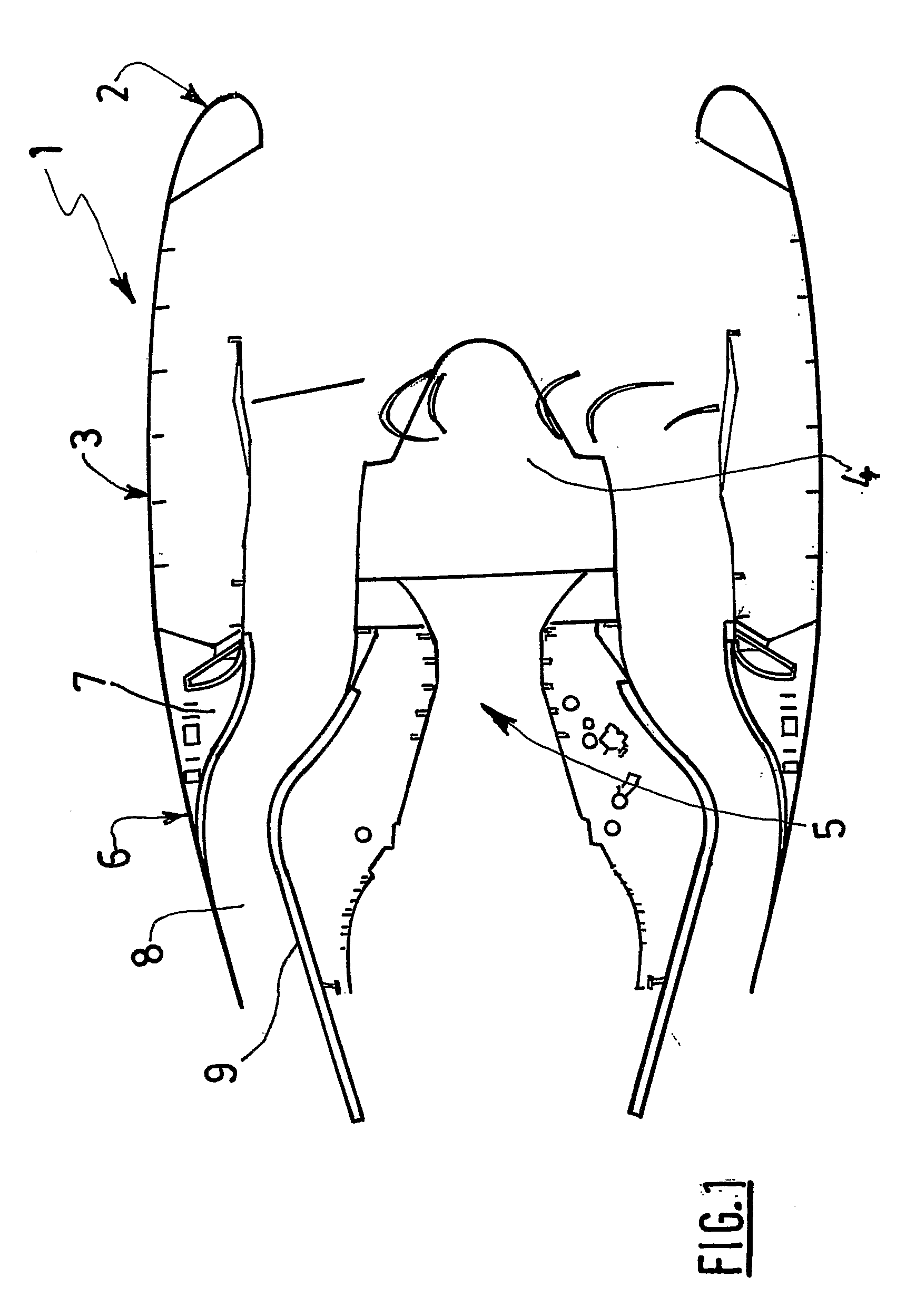
[0047]FIGS. 1 to 8 depict a nacelle according to the invention.

[0048]A nacelle 1, as shown in section in FIG. 1, comprises an upstream air intake structure 2, a middle structure 3 surrounding a fan 4 of a turbojet engine 5, and a downstream structure comprising, in a way known per se, an outer structure 6 known as the OFS, housing thrust reversal means 7 and which defines an annular flow duct 8 with a concentric inner structure (IFS) 9 surrounding a downstream part of the turbojet engine 5 extending to the rear of the fan 4.

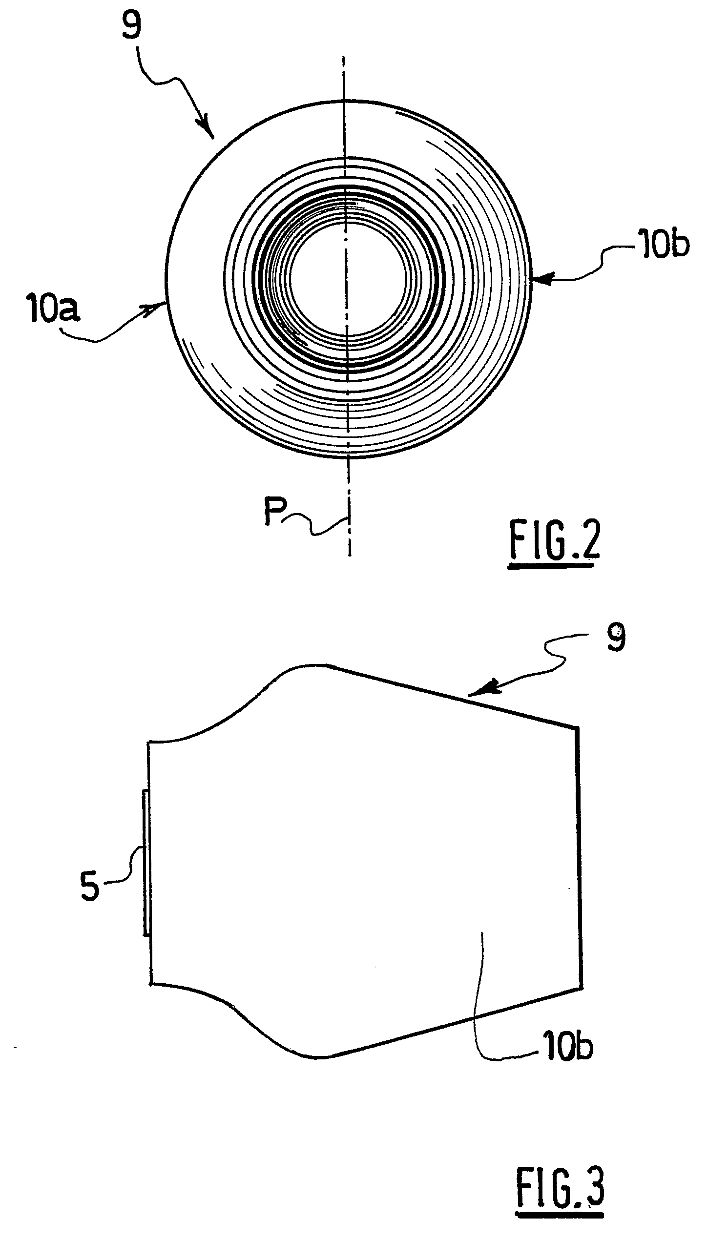
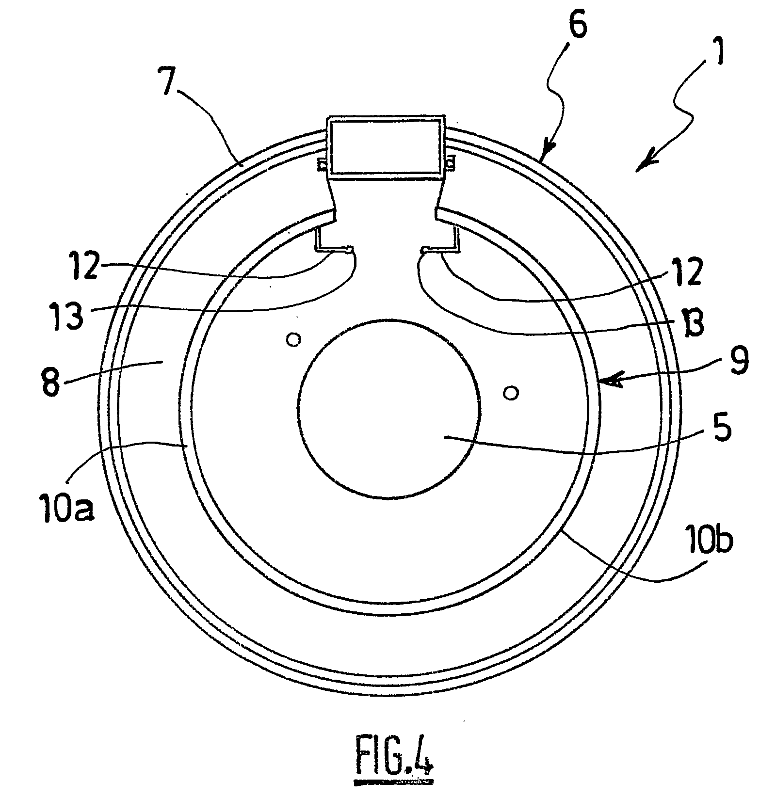
[0049]The nacelle inner structure 9, as illustrated in greater detail in FIGS. 2 and 3, is formed of two half-shells 10a and 10b of substantially semicylindrical shape, positioned one on each side of a longitudinal vertical plane P of symmetry of the nacelle.

[0050]In FIG. 3, the structure of the turbojet engine 5 is substantially hidden by the half-shells 10a and 10b of the inner structure 9.

[0051]Each half-shell 10a or 10b is attached to the outer structure 6 of...

second embodiment

[0063]FIGS. 9 to 15 set out the nacelle according to the invention comprising an inner structure 110. Only the modified inner structure 110 and the case of the fan 4 of the middle section 3 have been depicted for ease of understanding. The overall structure of the nacelle 1 applies.

[0064]It should be noted that, in FIGS. 9 to 11, the turbojet engine 5 is hidden by the inner structure 110 of the nacelle in the working position.

[0065]The inner structure 110 is formed of a fixed fairing part 114 extending longitudinally at the top, and of a mobile shell 113, of substantially cylindrical shape, surrounding the turbojet engine 5. The shell 113 has a slot 134 running longitudinally along the top and of a shape that complements that of the fixed fairing part 114.

[0066]The fixed fairing part 114 is fixed upstream (with reference to the direction in which the gases flow) to a frame 115 secured to the turbojet engine 5 and is attached, downstream, to the turbojet engine 5, via supporting link...


PUM


Abstract

The invention relates to a nacelle for a turbojet, of the type comprising a downstream structure having an outer structure (6) that defines, together with an inner concentric structure (9) for surrounding the downstream portion of the turbojet, an annular flow channel (8), characterised in that a portion at least of said inner structure (9) is mounted so as to be capable of a translation movement along the longitudinal axis of the nacelle so that it can move between a working position, in which the inner structure acts as a casing for the downstream portion of the turbojet, and a maintenance position in which the inner structure exposes said downstream portion of the turbojet.

Description

TECHNICAL FIELD OF THE INVENTION[0001]The invention relates to an airplane turbojet engine nacelle, of the type comprising a downstream structure comprising an outer structure which defines, with a concentric inner structure intended to surround a downstream part of the turbojet engine, an annular flow duct, which duct is also known as the flow path.BRIEF DISCUSSION OF RELATED ART[0002]An airplane is propelled by a number of turbojet engines each housed in a nacelle that also houses a collection of ancillary actuating devices associated with the operation thereof and performing various functions when the turbojet engine is operating or stationary. These ancillary actuating devices notably comprise a mechanical system for the actuation of thrust reversers.[0003]A nacelle generally has a tubular structure comprising an air intake upstream of the turbojet engine, a middle section intended to surround a fan of the turbojet engine, a downstream section housing thrust reversal means and i...

Claims


Application Information

Patent Timeline
Patent Type & Authority Applications(United States)
IPC IPC(8): F01D25/24
CPCB64D29/08F05D2230/80Y02T50/671F02K1/00Y02T50/60
Inventor VAUCHEL, GUY BERNARDHILLEREAU, NICOLASCOLLIER, JEROMECHOUARD, PIERRE-ALAINLEFORT, GUILLAUME
Owner SAFRAN NACELLES
Why Eureka
Try Eureka