Automatic balance adjusting centrifuge

a centrifuge and automatic technology, applied in the direction of centrifuges, instruments, mechanical equipment, etc., can solve the problems of imposing laborious work on users, unable to design/manufacture worm wheels to enhance the contact ratio between the tooth surface of the worm and the rack-type worm wheel, etc., to achieve the effect of enhancing the efficiency of space utilization and simplifying the structure of the centrifug

Active Publication Date: 2010-01-14
HANLAB CORP
View PDF8 Cites 57 Cited by
  • Summary
  • Abstract
  • Description
  • Claims
  • Application Information

AI Technical Summary

Benefits of technology

[0021]According to the automatic balance adjusting centrifuge of the present invention, the adoption of a length sensor and the direct connection between a balance weight and a motor shaft enable to transfer the balance weight precisely and correctly and also to simplify the structure of the centrifuge. Furthermore, the efficiency of space utilization is enhanced because a rotational shaft of a motor for transferring the balance weight is disposed in the radial direction of the rotating arm.

Problems solved by technology

In the operation of the centrifuge, imbalance of the centrifugal force is inevitably created by the weight differences among buckets due to the discrepancy in the number of samples within each bucket or in the total weight.
However, the conventional centrifuge without the automatic balancing function brought about a problem of imposing the laborious works on users, such as measuring the weight of each sample manually to load the samples with an identical weight on a rotor symmetrically.
However, in the conventional automatic balance adjusting centrifuge as described in the above, there has been a difficulty of designing / manufacturing for enhancing the contact ratio of tooth surface between a worm and a rack-type worm wheel, because it uses a worm shaft-coupled with a balance weight transfer motor, a worm gear tooth-coupled with the worm, and a balance weight transfer shaft coaxial-coupled with the worm gear, as balance weight transferring means.
Furthermore, there have been some problems such that accuracy falls down because of analogizing the current position of a balance weight with the number of rotation of the balance weight transfer motor implemented simply by a step motor, structure is complicated because of separating a balance weight transfer shaft from a motor shaft, and the efficiency of space utilization is low because of installing the balance weight transfer motor as the shaft faces to vertical direction.

Method used


Image

  • Automatic balance adjusting centrifuge
  • Automatic balance adjusting centrifuge
  • Automatic balance adjusting centrifuge

Examples


Embodiment Construction

[0030]In the following, preferred embodiments of the automatic balance adjusting centrifuge of the present invention are described in detail referring to the accompanying drawings.

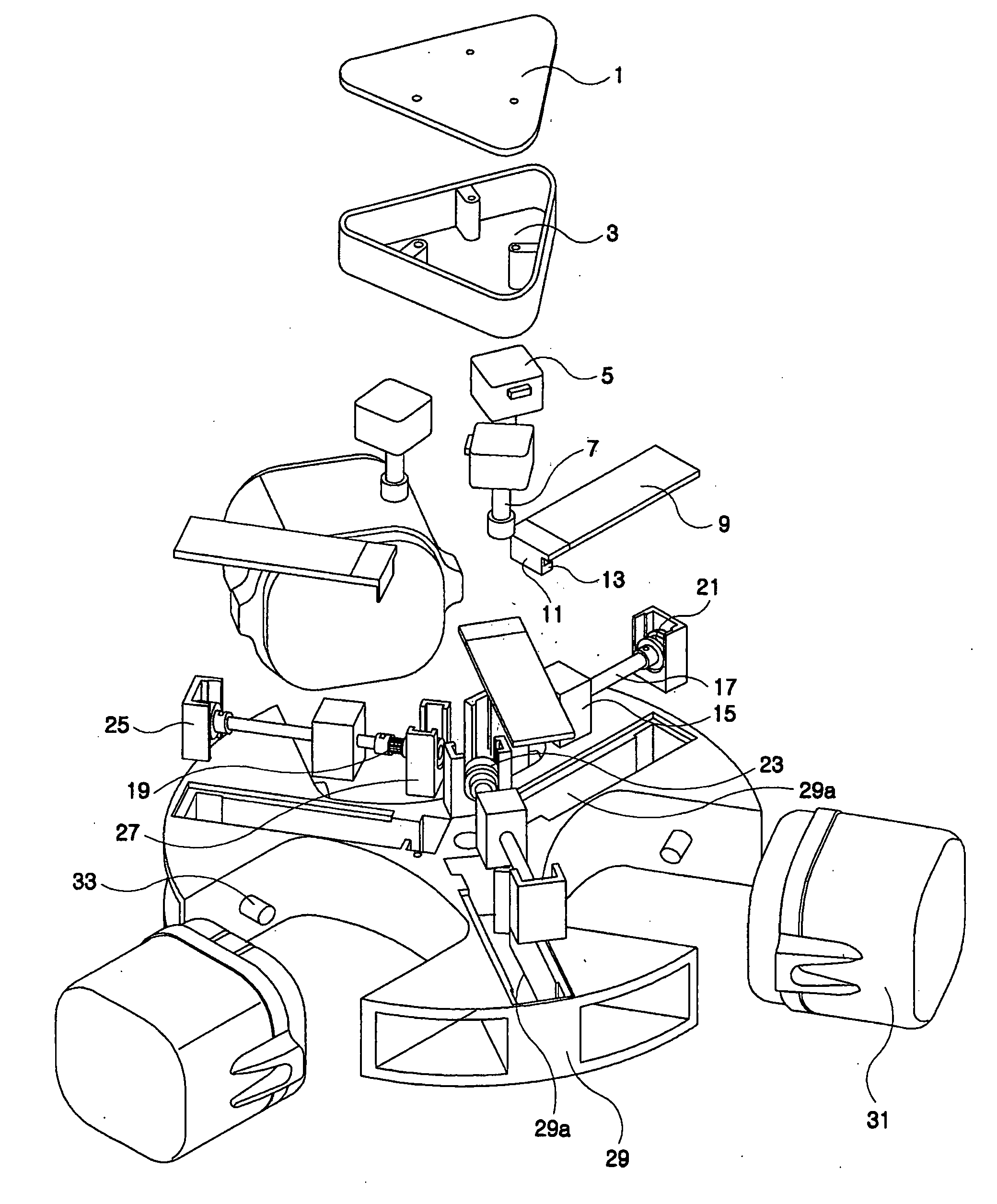
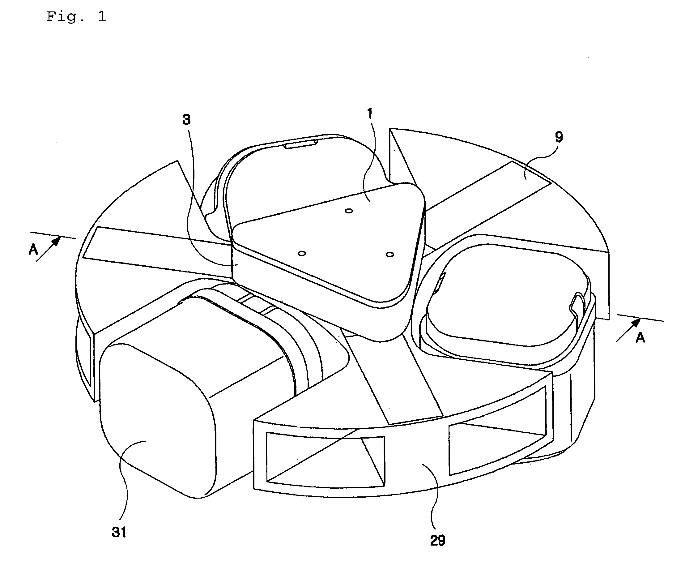
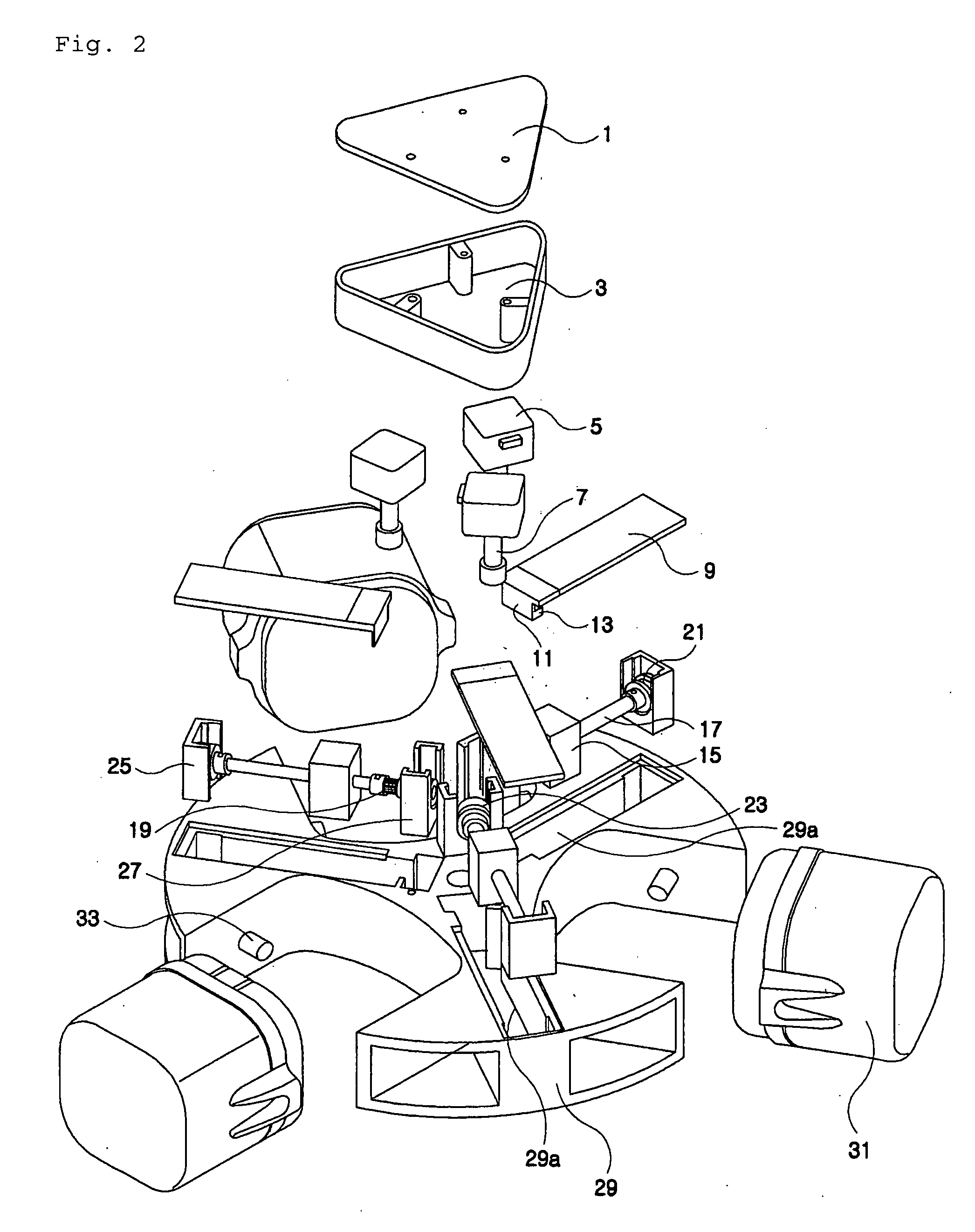
[0031]FIG. 4 is a plane view showing a rotor of an automatic balance adjusting centrifuge according to one embodiment of the present invention. As shown in FIG. 4, the automatic balance adjusting centrifuge of the present invention can include a rotor having three rotating arms 29′ to support buckets 31′ loading samples as described in PI, and a balance weight transfer mechanism 100, including a balance weight 160 to compensate for the weight imbalance of the rotor and a balance weight transfer motor 120 to transfer the balance weight 160 horizontally along the radial direction of each rotating arm 29′, is installed in each rotating arm 29′.

[0032]In the configuration described in the above, the rotating arm 29′ can be formed by cutting away some portion equi-angularly, which is supposed to install buckets ...


PUM


Abstract

The present invention relates to the automatic balance adjusting centrifuge that enhances the efficiency of space utilization by simplifying the structure as well as supports a precise movement by improving the structure of the balance weight transport apparatus in the automatic balance adjusting centrifuge that compensates the unbalance of the centrifugal force by transferring the balance weight equipped in the rotor rotational arm.
According to the automatic balance adjusting centrifuge of the present invention, the structure is simplified as well as the precise and exact transfer of the balance weight is possible by connecting the balance weight with the axis of the motor directly and adopting the length sensor. Furthermore, the efficiency of space utilization is enhanced because the axis of rotation of the balance weight transfer motor is in radial direction of the rotational arm.

Description

CROSS REFERENCE TO RELATED APPLICATIONS[0001]This application claims priority from Korean patent application No. 10-2008-0067109 filed on Jul. 10, 2008, all of which is incorporated herein by reference in its entirety for all purposes.BACKGROUND OF THE INVENTION[0002]1. Field of the Invention[0003]The present invention relates to an automatic balance adjusting centrifuge, and particularly to an automatic balance adjusting centrifuge compensating for the imbalance of the centrifugal force by transferring balance weights equipped in rotating arms.[0004]2. Description of the Related Art[0005]As is well known, a centrifuge is an essential equipment which is widely used over medical and physiochemical fields, and is an instrument which separates sample elements by rotating a rotor equipped with buckets containing samples at a high speed to provide the samples with high centrifugal acceleration. Thus, high density elements in the samples are placed at the outer layer along the radial dire...

Claims


Application Information

Patent Timeline
Patent Type & Authority Applications(United States)
IPC IPC(8): B04B13/00
CPCB04B9/146Y10T74/2109G01M1/36
Inventor RYU, HEUIGEUNKWON, OHHUNLEE, SUNGHYUKLEE, SANGHOON
Owner HANLAB CORP
Why Eureka
Try Eureka