
Multi-chamber container

a multi-chamber, container technology, applied in the field of multi-chamber containers, can solve the problems of reducing the sterilization efficiency compared with the heat treatment effect of wet type containers

Inactive Publication Date: 2010-01-14
AJINOMOTO CO INC
View PDF5 Cites 8 Cited by
  • Summary
  • Abstract
  • Description
  • Claims
  • Application Information

AI Technical Summary

Benefits of technology

The present invention aims to prevent the possibility of an erroneous operation that an infusion is done under a non-opened condition without reducing the desired sterilizing capability. This is achieved by controlling the size of a vent hole in a second weak seal of a medical bag, which is essential for maintaining sterilization quality and preventing liquid flow. The challenge is to design the vent hole under a material to material base to ensure the desired size control.

Problems solved by technology

Namely, a piercing of the rubber plug at the outlet port without opening the weak seal causes such an erroneous operation to be occurred that only the medical liquid at the partition located at the partition adjacent the outlet port is given.
If such a provision of the vent hole in the second weak seal were eliminated, an air merely would occupy at the outlet port, so that a dry heat treatment is only attained, resulting in a reduced sterilizing efficiency as compared with that as obtained by the wet type heat treatment.

Method used


Image

  • Multi-chamber container
  • Multi-chamber container
  • Multi-chamber container

Examples


Embodiment Construction

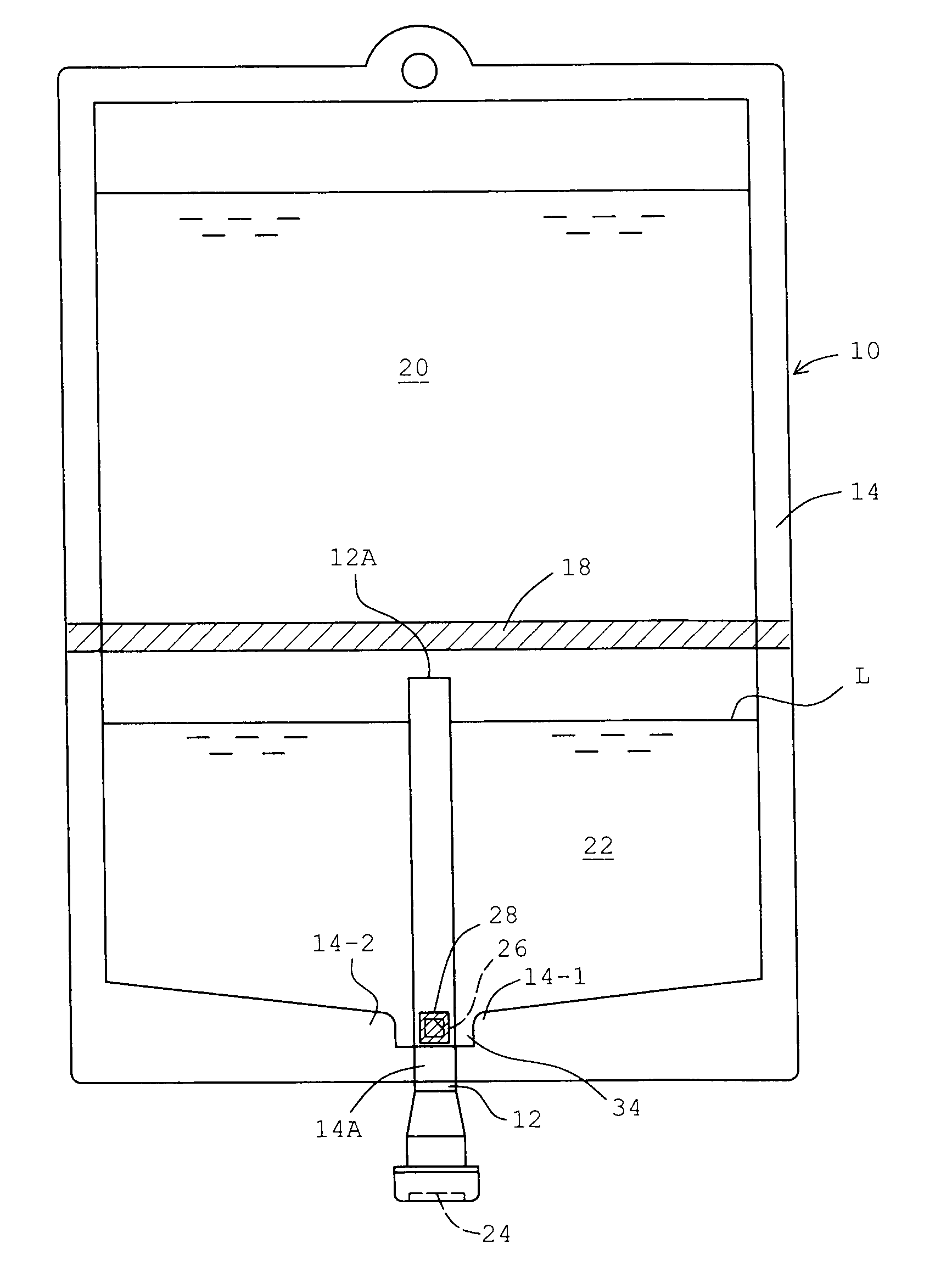
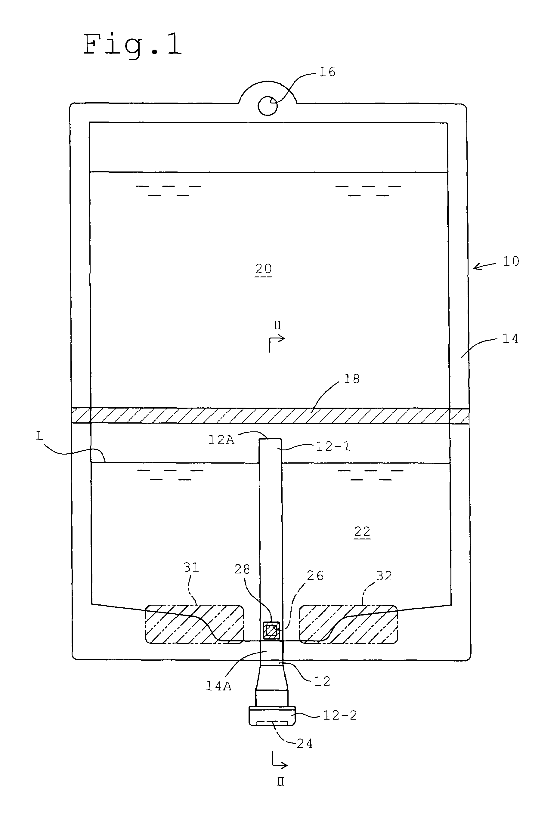
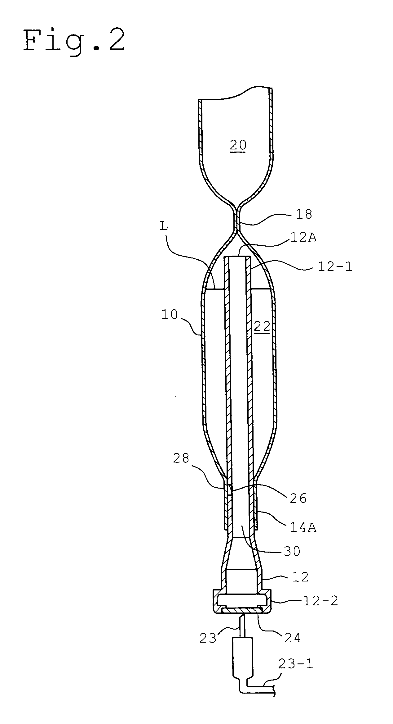
[0043]In FIG. 1, a multi-chamber container includes a flat shaped medical bag 10 for storing therein with medical liquids and an outlet port mounted at the outer periphery of the medical bag 10. The medical bag 10 is formed from a soft synthetic resin film of a multi layer structure, such as a polyethylene film (flexible film of the present invention) of a thickness of a value such as 300 micron. Two cuts of synthetic resin film are provided, which are, at their outer peripheries, pressed at a temperature (about 130° C. in case of polyethylene) sufficiently higher than its softening temperature, in order to create a strong seal (outer peripheral non-separable weld) 14, so that a bag of a substantial rectangular shape is obtained. Formed at the outer peripheral weld 14 is a suspension hole 16, by which the medical bag 10 is suspended and held by a infusion stand for practicing an infusion operation, such as intravenous feeding.

[0044]At a middle along the vertical direction of the med...


PUM

PropertyMeasurementUnit
thicknessaaaaaaaaaa
temperatureaaaaaaaaaa

Abstract

A medical bag having a seal separating its inner space into a plurality of partitions for separate sealed storage of medical liquids and aiming for preventing erroneous operation that an infusion is practiced under a non-opened condition without worsening sterilizing performance during the production of the bag.A weak seal 18 is formed by welding the top and bottom film layers of medical bag 10 along the entire width of the medical bag, so that partitions 20 and 22 are formed at the upper and lower part of the weak seal 18. An outlet port 12 is mounted to the medical bag at a strong seal 14A. The outlet port 12 is extended in the lower chamber 22 to a location adjacent the weak seal 18, so that top end 12A is opened to the lower chamber 22 at a location above the liquid level L. The outlet port 12 is, at its bottom end, formed with a communication hole 26, while the shaded part (valve portion 28) at the inner face of the medical bag is welded to the opposite surface of the outlet port 12, thereby closing the communication hole 26. The welding strength of the valve portion 28 is slightly stronger than that of the weak seal 18.

Description

TECHNICAL FIELD[0001]The present invention relates to a multi-chamber container as a medical bag having an inner cavity divided by a weak seal (separable weld or partition wall) into a plurality of partitions for storing therein with medical liquids independently and an outlet port for discharging the medical liquids after mixed from the respective partitions and also relates to a method for discharging medicines.BACKGROUND TECHNOLOGY[0002]Known is a multi-chamber container for an infusion, having a medical bag made of soft films and a weak seal as constructed by opposed faces of the films welded at a relatively low temperature in a manner that the bag is divided into a plurality of partitions for storing different medical liquids, respectively. An outlet port as a plastic mold product is arranged at the outer periphery of the bag. The outlet port forms a tubular shape having an inner cavity, which has a first end opened to one of the partitions and a second end fitted with a rubber...

Claims


Application Information

Patent Timeline
Patent Type & Authority Applications(United States)
IPC IPC(8): A61J1/10
CPCA61J1/10A61J1/1475A61J1/2093A61J2001/2024B29C66/53262B29C65/02B29C65/76B29L2031/7148A61M5/162A61J1/2024B29C66/1122B29C66/24221B29C66/133A61J1/05
Inventor MURAMATSU, YASUHIRO
Owner AJINOMOTO CO INC
Learn More