Robot

a robot and hand device technology, applied in the field of robots, can solve the problems of inferior applicability of the gripper hand device to the work treating various goods, and achieve the effect of improving the applicability of the gripper hand device to the work of various goods

Inactive Publication Date: 2010-01-14
YASKAWA DENKI KK
View PDF16 Cites 32 Cited by
  • Summary
  • Abstract
  • Description
  • Claims
  • Application Information

AI Technical Summary

Benefits of technology

[0007]According to one aspect of the present invention, a robot comprises: a base unit; at least two link mechanisms arranged on the base unit; drive units capable of bending and extending the link mechanisms; and a control unit controlling the drive units, wherein at least one of the drive units has a drive force larger than those of the other drive units, and the other drive units are passively displaced by an external force larger than their own drive forces, wherein the robot further comprises extension suppressing units suppressing displacement of the other drive units in directions of their extensions at predetermined positions.
[0008]According to another aspect of the present invention, a control method of a robot including a base unit and at least two link mechanisms arranged on the base unit enables the link mechanism to be bent and extended with the drive units and controls the drive units with a control unit, wherein the control unit controls the drive units lest adjacent ones of the extension suppressing units should touch each other when a manipulation object is a small-sized light load, and controls the drive units so that the adjacent ones of the extension suppressing units touch each other when the manipulation object is a large-sized heavy load.
[0009]According to another aspect of the present invention, a robot comprises: a base unit; at least two link mechanisms arranged on the base unit; drive units capable of bending and extending the link mechanisms; and a control unit controlling the drive units, wherein the drive units having drive forces larger than those of the drive units capable of bending and extending the link mechanisms are arranged on the base unit, and the drive units arranged on the base unit transmit power to the link mechanisms with a power transmitting mechanism.
[0010]According to further aspect of the present invention, a control method of a robot including a base unit and at least two link mechanisms arranged on the base unit enables the link mechanisms to be bent and extended with the drive units and controls the drive units with a control unit, wherein a superior control apparatus outputting an instruction to the control unit obtains information of outside dimensions, weight, and the like of an object, in advance by image recognition or detection means, such as an identification tag, and informs the control unit of the information, wherein the control unit controls the drive units by a driving operation according to the information.
[0011]According to another aspect of the present invention, a robot comprises: a base unit; at least two link mechanisms arranged on the base unit; drive units capable of bending and extending the link mechanisms; and a control unit controlling the drive units, wherein adjacent ones of the link mechanisms are joined to each other.
[0012]According to another aspect of the present invention, a control method of a robot including a base unit and at least two link mechanisms arranged on the base unit enables the link mechanisms to be bent and extended with the drive units and controls the drive units with a control unit, wherein the link mechanisms perform synchronous operations by a cooperative control when the link mechanisms operates in a state of being joined to each other.

Problems solved by technology

However, since the gripper type hand device has the simple configuration, the gripper type hand device has a disadvantage of being inferior in the applicability to the work treating various goods.

Method used


Image

  • Robot
  • Robot
  • Robot

Examples


embodiments 1

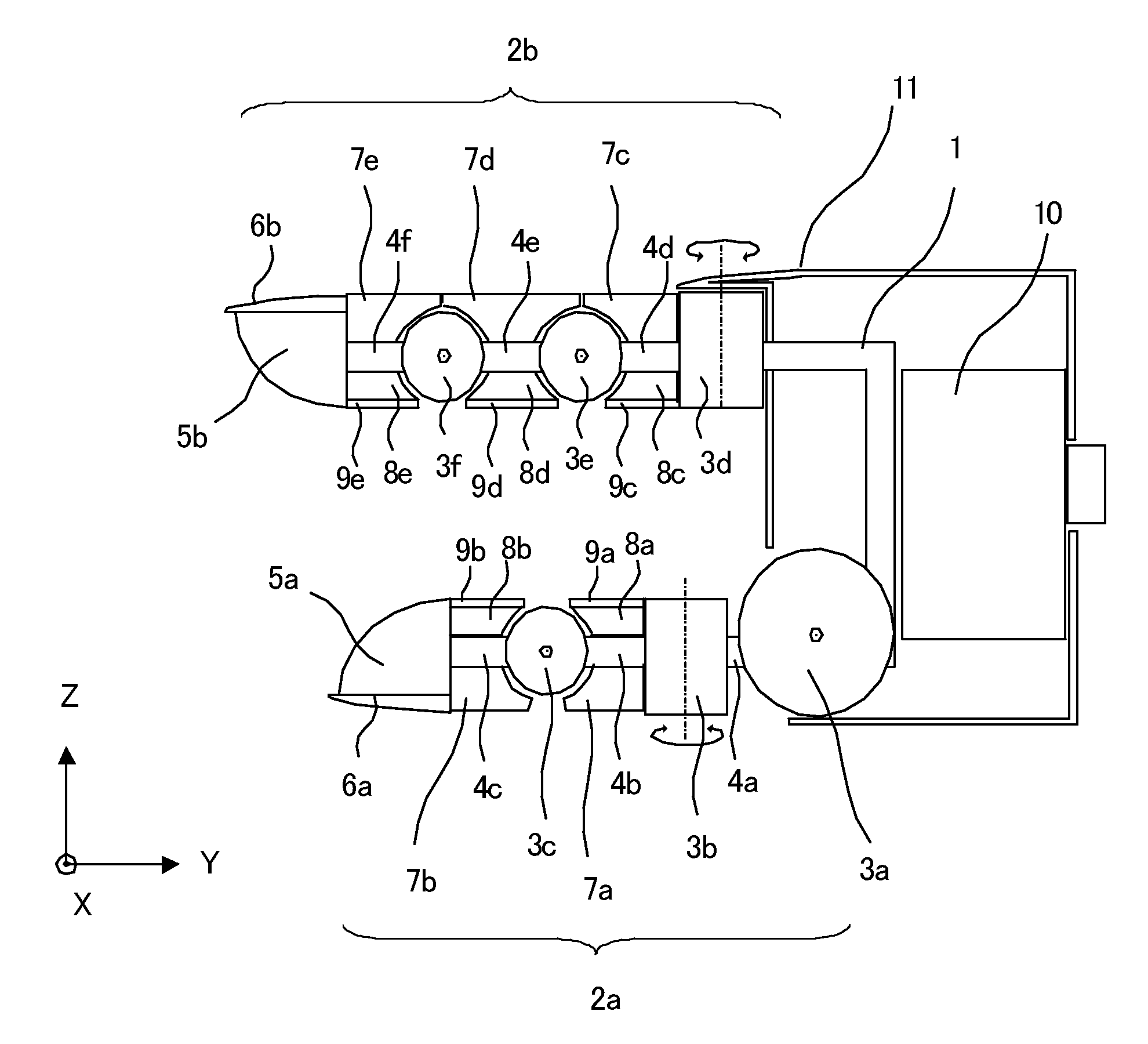
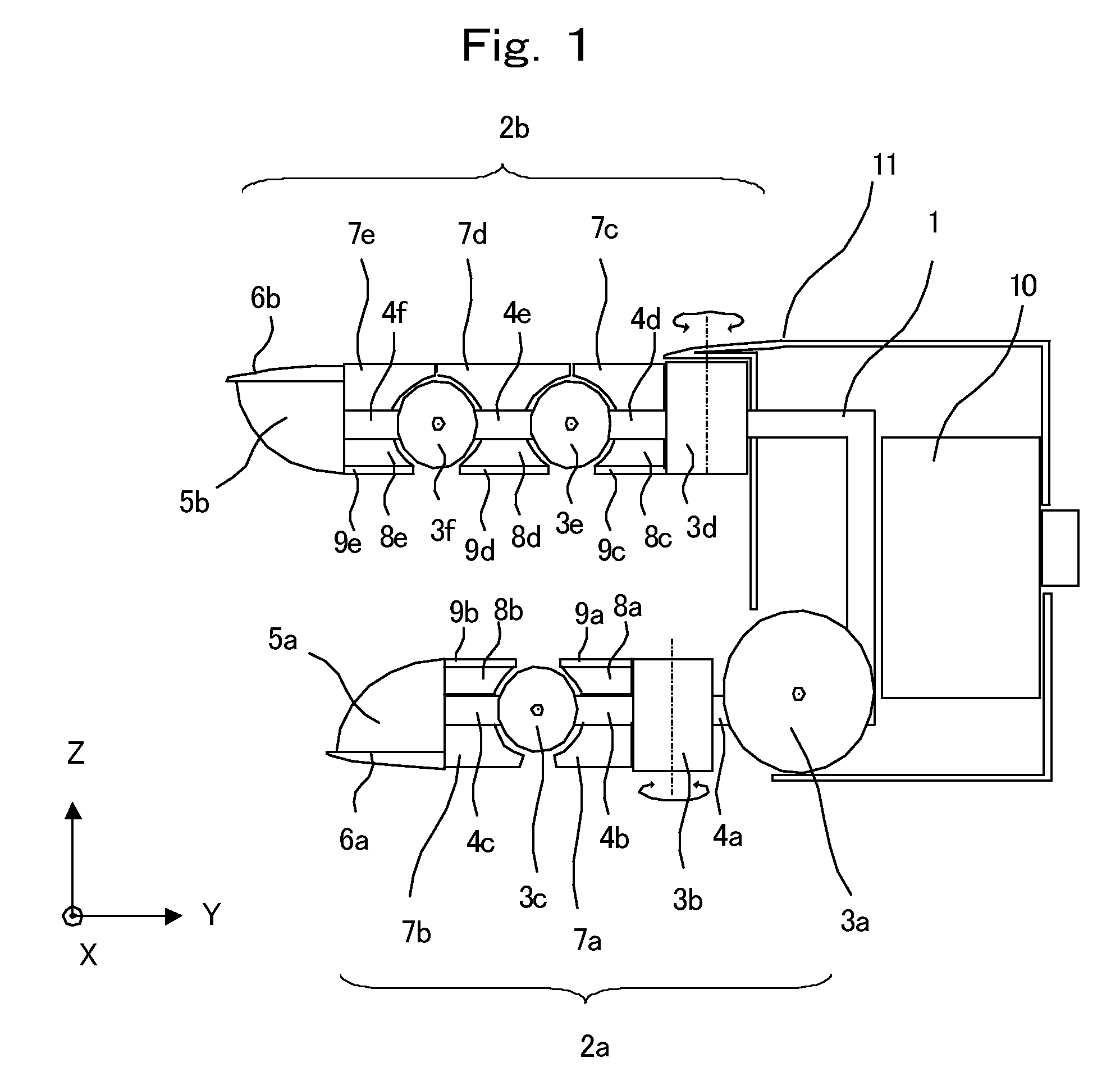
[0030]FIG. 1 is a side view showing the configuration of a hand device of the present invention. In FIG. 1, a reference numeral 1 denotes a hand base unit, and reference numerals 2a and 2b denote finger units arranged on the hand base unit 1. The finger unit 2a corresponds to a thumb of a human being, and the finger unit 2b corresponds to a forefinger of a human being. Both the finger units 2a and 2b are almost opposed. The finger unit 2a is configured to join finger drive units 3a, 3b, and 3c to each other with links 4a, 4b, and 4c, respectively. A finger tip portion 5a is attached to the end of the link 4c, and further a nail portion 6a is attached onto the outer surface of the finger tip portion 5a. The finger unit 2b is configured to join finger drive units 3d, 3e, and 3f with links 4d, 4e, and 4f, respectively. A finger tip portion 5b is attached to the end of the link 4f, and further a nail portion 6b is attached onto the outer surface of the finger tip portion 5b. The finger ...

embodiment 2

[0048]FIG. 7 is a configuration diagram showing an example of the multifingered robot hand device of the present invention. In FIG. 7, a reference numeral 1000 denotes a multifingered hand unit of the multifingered robot hand device according to the present invention, and the multifingered hand unit 1000 includes fingers 1100 and 1200, each having three joints. Incidentally, although the case of two fingers and three joints per finger is shown in FIG. 7 for simplification, the number of the fingers and the number of joints are not limited to the above numbers.

[0049]The present invention is different from the embodiment 1 in that a pulley is provided to each figure drive unit provided in each joint, and that the pulley of each finger drive unit provided in each joint is driven by a large-sized actuator provided in a base unit to make it possible to perform wide operations from an accurate operation to the manipulation of a heavy load.

[0050]In FIG. 7, reference numerals 1101, 1102, an...

embodiment 3

[0068]FIG. 10 is a view showing the configuration of the external power unit 200 of a third embodiment of the present invention. The reference numerals 201-204 denote the same components as those of the second embodiment. Reference numerals 214-217 denote power cutting units, which perform the connection and cutting of the power transmission between the motors 201-204 and pulleys 205-208 on the basis of the instructions from the superior control apparatus 301. The power cutting units 214-217 is each composed of, for example, an electromagnetic clutch or an electromagnetic brake. That is, each of the power cutting units 214-217 has a facing structure, one surface of which is made of a ferromagnetic material or a soft magnetic material, the other surface of which is provided with an electromagnet on the opposed surface. The configurations of the clutch mechanism and the brake mechanism can be obtained by means of an attracting force generated by the electrification to the electromagne...


PUM

PropertyMeasurementUnit
drive forceaaaaaaaaaa
external forceaaaaaaaaaa
drive forcesaaaaaaaaaa

Abstract

A robot includes a base unit, at least two link mechanisms arranged on the base unit, drive units capable of bending and expanding the link mechanisms, and a control unit controlling the drive units. At least one drive unit has a drive force larger than those of the other drive units, and the other drive units are passively displaced by external forces larger than their own drive forces.

Description

CROSS-REFERENCE TO RELATED APPLICATIONS[0001]The present application is a continuation application of PCT / JP2008 / 055635, filed Mar. 26, 2008, which claims priority to Japanese Patent Application No. 2007-097255, filed Apr. 3, 2007. The contents of these applications are incorporated herein by reference in their entirety.BACKGROUND OF THE INVENTION[0002]1. Field of the Invention[0003]The present invention relates to a robot capable of dealing with a heavily-loaded load despite its small shape and capable of realizing various patterns of manipulation operations with a high degree of accuracy.[0004]2. Discussion of the Background[0005]An industrial robot is furnished with a hand device for performing various kinds of work, and a gripper type hand device has been widely used as the hand device. As the configuration of the gripper type hand device, for example, the configuration of swingably supporting a pair of flat plates with one shaft or parallel two shafts to make the flat plates pe...

Claims


Application Information

Patent Timeline
Patent Type & Authority Applications(United States)
IPC IPC(8): G06F19/00B25J15/08
CPCB25J9/104B25J9/1612B25J15/0009Y10T29/49826Y10T74/20305Y10T74/20329Y10T74/20317
Inventor MATSUKUMA, KENJINAKAMURA, TAKAYUKIYOKOYAMA, KAZUHIKOFUKUDOME, KAZUHIRO
Owner YASKAWA DENKI KK
Why Eureka
Try Eureka