Tire noise reduction device and pneumatic tire

Active Publication Date: 2010-01-21
YOKOHAMA RUBBER CO LTD
View PDF15 Cites 27 Cited by
  • Summary
  • Abstract
  • Description
  • Claims
  • Application Information

AI Technical Summary

Benefits of technology

[0009]According to the present invention mentioned above, the second sound absorbing layer of the sound absorbing member is lower in density than before. Therefore, the mass of the sound absorbing member is reduced, allowing weight lightening to be achieved.
[0010]The tear strength (N/cm) per unit density (kg/m3) of the first sound absorbing layer disposed on the tire inner surface side is specified as mentioned above, whereby occurrence of chipping and cracking to the first sound absorbing layer can effectively be suppress

Problems solved by technology

A cavity resonance phenomenon that occurs in an airtightly sealed tire cavity formed between the rim of a wheel and a pneumatic tire mounted on the rim is a major factor of tire noise.
On the other hand, the sound absorbing member has chipping and cracking arising from friction against the inner surface of the tire which is repeatedly deformed during running.
How

Method used


Image

  • Tire noise reduction device and pneumatic tire
  • Tire noise reduction device and pneumatic tire
  • Tire noise reduction device and pneumatic tire

Examples


example

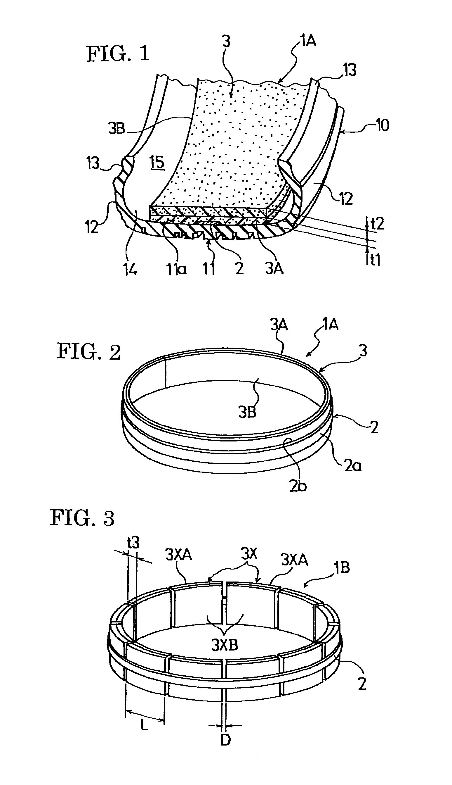
[0069]Prepared respectively were tire noise reduction devices according to the tire noise reduction devices 1 and 2 of the present invention (present examples 1 and 2), conventional tire noise reduction device (conventional example) and comparative tire noise reduction device (comparative example), the tire noise reduction devices 1 and 2 of the present invention each having a sound absorbing member of flexible polyurethane foam with a thickness of 15 mm and with a width of 150 mm comprising a first sound absorbing layer and a second sound absorbing layer and having a structure shown in FIG. 2 in which the thickness, density tear strength and tear strength / density of each of the first sound absorbing layer and second sound absorbing layer were as shown in Table 1, the conventional tire noise reduction device having the same structure as the tire noise reduction device 1 of the present invention except that the sound absorbing member consisted of a first sound absorbing layer and the...


PUM


Abstract

There is provided a tire noise reduction device and a pneumatic tire, in which weight can be reduced while sound absorbing characteristics are maintained and durability is improved.
The tire noise reduction device 1A of the present invention includes a sound absorbing member 3 of flexible polyurethane foam to be attached to an inner surface of a tire facing a cavity of the tire. The sound absorbing member 3 comprises a first sound absorbing layer 3A placed on a tire inner surface side thereof. The first sound absorbing layer 3A has a tear strength (N/cm) per unit density (kg/m3) which is equal to or more than 0.30. The second sound absorbing layer 3B has a density which is lower than that of the first sound absorbing layer 3A.

Description

TECHNICAL FIELD[0001]The present invention relates to a tire noise reduction device and a pneumatic tire having the tire noise reduction device, and more particularly to a tire noise reduction device and a pneumatic tire capable of reducing weight while improving durability.TECHNICAL BACKGROUND[0002]A cavity resonance phenomenon that occurs in an airtightly sealed tire cavity formed between the rim of a wheel and a pneumatic tire mounted on the rim is a major factor of tire noise. Noise around 250 Hz regularly heard during running or impulsive sounds generated in running over joint lines or the like of a road, for example, is involved with the cavity resonance phenomenon.[0003]As a technique for reducing noise caused by such a cavity resonance phenomenon, there is known, for example, a technique such that a sound absorbing member of a porous material such as urethane resin foam is disposed on the inner surface of a tire facing the tire cavity to thereby reduce noise caused by the ca...

Claims


Application Information

Patent Timeline
IPC IPC(8): B60C5/00
CPCB60C19/002Y10T152/10495Y10T152/10054Y10T152/10036
Inventor TANNO, ATSUSHITSUJIMOTO, HIROYUKI
Owner YOKOHAMA RUBBER CO LTD
Why Eureka
Try Eureka