Ion Plasma Electron Emitters for a Melting Furnace

a technology of plasma electron emitters and melting furnaces, which is applied in the direction of muffle furnaces, furnaces, lighting and heating apparatus, etc., can solve the problems of significant complicating alloy production

Inactive Publication Date: 2010-01-21
ATI PROPERTIES
View PDF72 Cites 32 Cited by
  • Summary
  • Abstract
  • Description
  • Claims
  • Application Information

AI Technical Summary

Benefits of technology

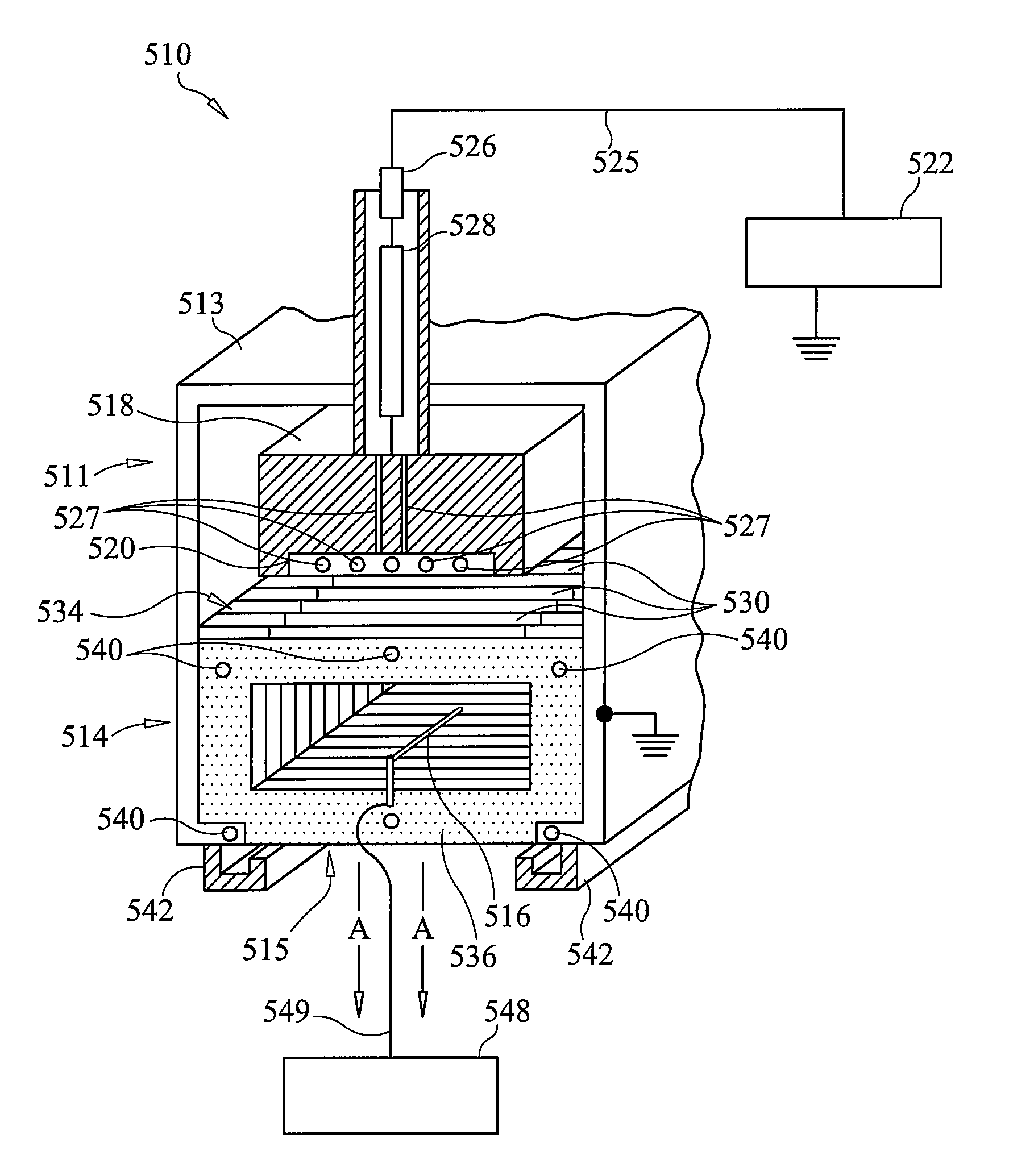
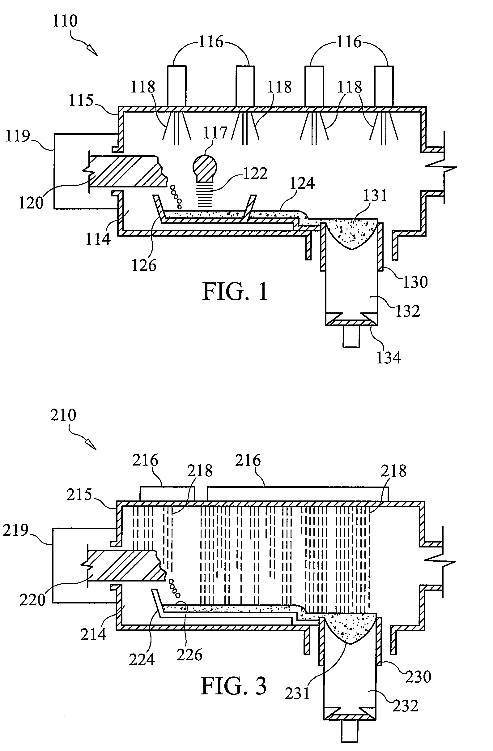
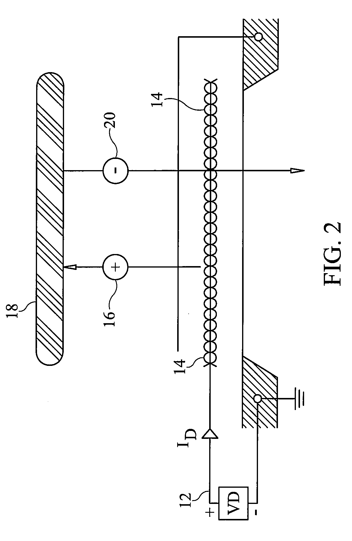
[0015]According to still a further aspect of the present disclosure, a method of processing a material is provided. The method comprises introducing a material comprising at least one of a metal and a metallic alloy into a furnace chamber maintained at a low pressure relative to atmospheric pressure, and generating a first electron field having a first cross-sectional area using at least a first ion plasma electron emitter. The method further comprises subjecting the material within the furnace chamber to the first electron field to heat the material to a temperature above a melting temperature of the material, and generating a second electron field having a second cross-sectional area using a second ion plasma electron emitter. The method further comprises subjecting at least one of any solid condensate within the material, any solidified portions of the material, and regions of a solidifying ingot to the second electron field, using a steering system, to melt or heat at least one of the solid condensate, the solidified portions, and the regions of

Problems solved by technology

Undesirable evaporation must be factored into production and may significa

Method used


Image

  • Ion Plasma Electron Emitters for a Melting Furnace
  • Ion Plasma Electron Emitters for a Melting Furnace
  • Ion Plasma Electron Emitters for a Melting Furnace

Examples


Embodiment Construction

[0036]In the present description of non-limiting embodiments, other than in the operating examples or where otherwise indicated, all numbers expressing quantities or characteristics of ingredients and products, processing conditions, and the like are to be understood as being modified in all instances by the term “about”. Accordingly, unless indicated to the contrary, any numerical parameters set forth in the following description are approximations that may vary depending upon the desired properties one seeks to obtain in the apparatus and methods according to the present disclosure. At the very least, and not as an attempt to limit the application of the doctrine of equivalents to the scope of the claims, each numerical parameter should at least be construed in light of the number of reported significant digits and by applying ordinary rounding techniques.

[0037]Any patent, publication, or other disclosure material, in whole or in part, that is said to be incorporated by reference ...


PUM

PropertyMeasurementUnit
Electric potential / voltageaaaaaaaaaa
Pressureaaaaaaaaaa
Electrical conductivityaaaaaaaaaa

Abstract

An apparatus for melting an electrically conductive metallic material comprises an auxiliary ion plasma electron emitter configured to produce a focused electron field including a cross-sectional profile having a first shape. The apparatus further comprises a steering system configured to direct the focused electron field to impinge the focused electron field on at least a portion of the electrically conductive metallic material to at least one of melt or heat any solidified portions of the electrically conductive metallic material, any solid condensate within the electrically conductive metallic material, and/or regions of a solidifying ingot.

Description

CROSS-REFERENCE TO RELATED APPLICATIONS[0001]The present application claims priority under 35 U.S.C. §120 to, and is a continuation-in-part of, U.S. patent application Ser. No. 12 / 055,415, filed Mar. 26, 2008, which claims priority under 35 U.S.C. §119(e) to U.S. Provisional Patent Application Ser. No. 60 / 909,118, filed Mar. 30, 2007. Both of the referenced previously-filed applications are incorporated by reference herein in their entireties.BACKGROUND OF THE TECHNOLOGY[0002]1. Field of Technology[0003]The present disclosure relates to equipment and techniques for melting metals and metallic alloys (hereinafter “alloys”). The present disclosure more specifically relates to equipment and techniques utilizing electrons to melt or heat alloys and / or condensate formed within the melted alloys.[0004]2. Description of the Background of the Technology[0005]An alloy melting process involves preparing a charge of suitable materials and then melting the charge. The molten charge or “melt” ma...

Claims


Application Information

Patent Timeline
IPC IPC(8): B23K31/00
CPCB22D11/11C22B9/04C22B9/226C22B9/228F27B3/08F27B3/20C22B4/005F27D99/0006H01J37/077H01J37/305H01J2237/15H01J2237/3128F27B5/04
Inventor FORBES JONES, ROBIN M.
Owner ATI PROPERTIES
Why Eureka
Try Eureka