
Transmissive dynamic plasma steering apparatus for radiant electromagnetic energy

a technology of radiant electromagnetic energy and plasma steering, which is applied in plasma welding apparatus, plasma technique, manufacturing tools, etc., can solve the problems of not offering the required ninety to one hundred twenty degree steering angle needed for effective optical and infrared beam steering purposes, and present-day agile beam-steering technologies for these wavebands or smaller can not operate in the high power/high energy environment needed

Inactive Publication Date: 2009-12-01
AIR FORCE THE US SEC THE
View PDF10 Cites 11 Cited by
  • Summary
  • Abstract
  • Description
  • Claims
  • Application Information

AI Technical Summary

Benefits of technology

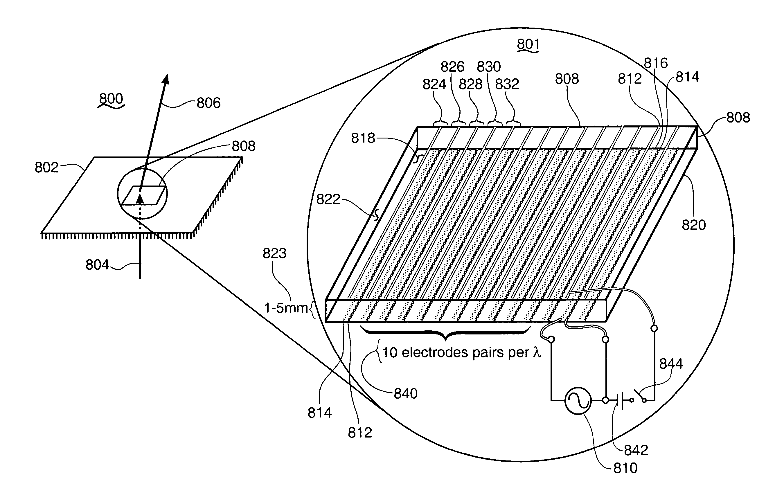
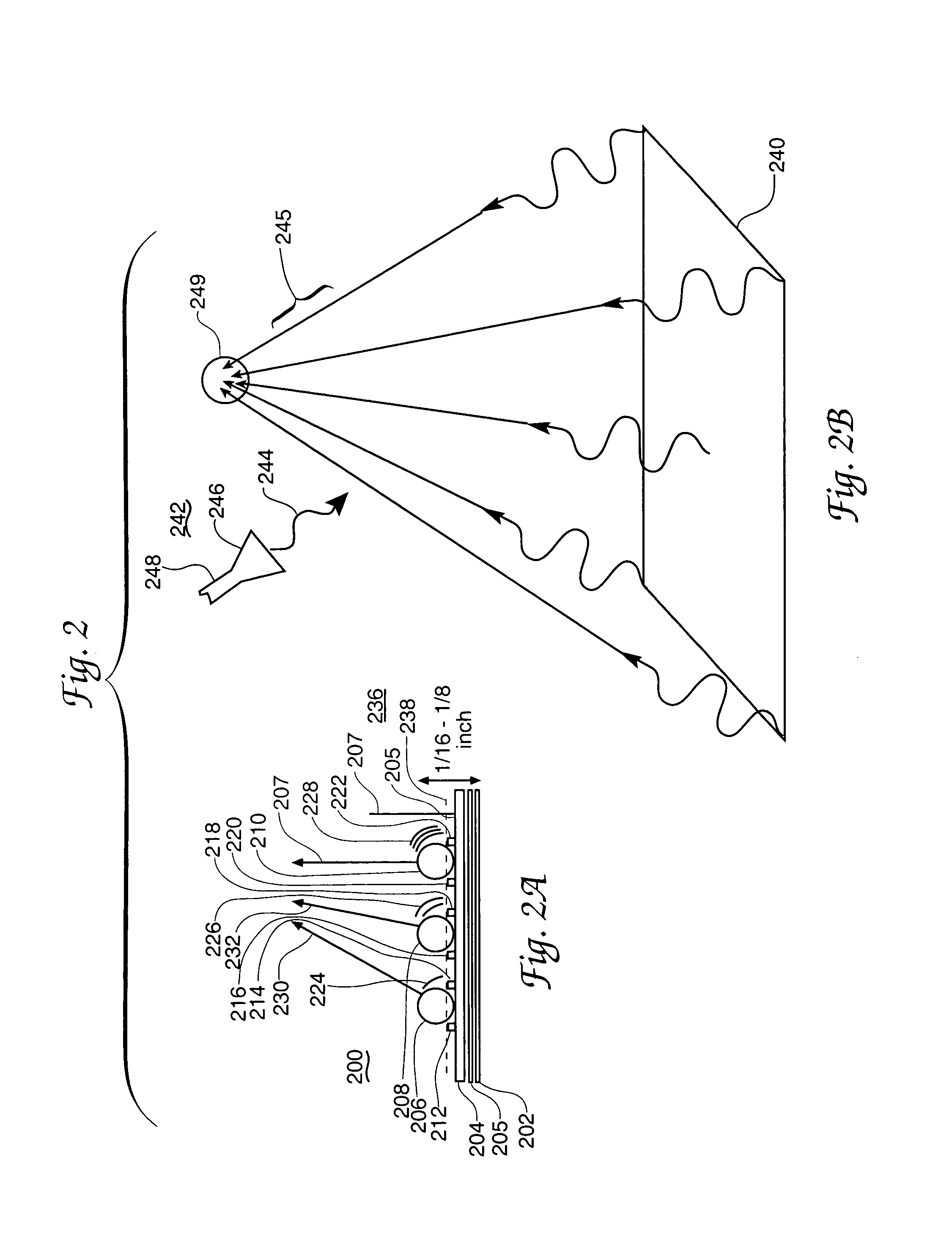
"The present invention provides a plasma-based system for steering radiant electromagnetic energy. The system can direct the energy of higher frequency radio waves and infrared waves using a plasma film. The system includes an ionized gas plasma film and a source of incident electromagnetic energy directed toward the plasma film. The system also has an array of ionized plasma electron density controlling modulation electrode pairs and a source of dynamically changing modulation voltage. The modulation voltage imparts a phase modulation directivity on refracted incident electromagnetic energy as a response of the plasma density and electron density in the plasma film. The technical effects of the invention include inertial free plasma-based steering of electromagnetic energy, suitable for a wide range of spectral ranges, and dynamic plasma transmissive steering of radiant optical wavelength energy."

Problems solved by technology

Current liquid crystal and Microelectromechanical Deformable Micromirror (MEMS-DM) technologies do not for example offer the required ninety to one hundred twenty degree steering angles needed for effective optical and infrared beam steering purposes.
Furthermore, present day agile beam-steering technologies for these wavebands or smaller can not operate in the high power / high energy environments needed for many projected military and non military uses expected in this spectral region with for example an infrared laser.

Method used


Image

  • Transmissive dynamic plasma steering apparatus for radiant electromagnetic energy
  • Transmissive dynamic plasma steering apparatus for radiant electromagnetic energy
  • Transmissive dynamic plasma steering apparatus for radiant electromagnetic energy

Examples


Embodiment Construction

[0038]One way in which the present invention may be appreciated is to consider that in many transmitting antenna arrangements it is common practice to energize plural elements of the antenna with electrical signals that are phase adjusted with respect to each other in order to steer the output beam of the antenna into a particular direction with respect to the antenna axis. Such steering may be accomplished in a fixed manner or may be provided with changeable adjustments in order to dynamically redirect the antenna's output, even in real time. For present purposes it is significant to note that in such steering arrangements it is common practice to perform the needed signal phase adjustments by electrical means, that is, through use of components located in the electrical signal paths leading to the antenna elements. In accordance with the present invention, however, such signal phase adjustment by electrical means and its accomplishment prior to arrival at the system antenna may be...


PUM

PropertyMeasurementUnit
steering anglesaaaaaaaaaa
sizeaaaaaaaaaa
sizeaaaaaaaaaa

Abstract

An ionized plasma based radiant electromagnetic energy steering or diverting apparatus wherein controlled differences in plasma density and resulting plasma electron density achieve phase shift, reflection or refraction of the controlled radiant electromagnetic energy. Plasma density determination through use of selected plasma control electrode electrical potentials and hence by the waveforms applied to plasma-adjacent electrodes is employed. Plasma controlled radiant electromagnetic energy is thereby usable for inertia free steering of a radar beam or for other applications of radiant electromagnetic energy. Radiant electromagnetic energy control by way of pass-through refraction of the energy and reflection of the energy directly from the plasma and also by reflection involving a reflector element are included. Radio frequency and optical electromagnetic energy wavelengths for the radiant electromagnetic energy are included.

Description

RIGHTS OF THE GOVERNMENT[0001]The invention described herein may be manufactured and used by or for the Government of the United States for all governmental purposes without the payment of any royalty.CROSS REFERENCE TO RELATED PATENT DOCUMENTS[0002]The present document is somewhat related to the co-pending and commonly assigned patent application documents “DYNAMIC PLASMA STEERING METHOD FOR RADIANT ELECTROMAGNETIC ENERGY”, Ser. No. 11 / 518,750; “TRANSMISSIVE DYNAMIC PLASMA STEERING METHOD FOR RADIANT ELECTROMAGNETIC ENERGY”, Ser. No. 11 / 518,742; and “REFLECTIVE DYNAMIC PLASMA STEERING APPARATUS FOR RADIANT ELECTROMAGNETIC ENERGY”, Ser. No. 11 / 518,749; which are each filed of even date herewith. The contents of these related even filing date applications are hereby incorporated by reference herein.BACKGROUND OF THE INVENTION[0003]The ability to steer or to controllably direct the path or the trajectory of a beam of radiant electromagnetic energy is a significantly useful tool in num...

Claims


Application Information

Patent Timeline
Patent Type & Authority Patents(United States)
IPC IPC(8): B23K10/00
CPCH05H1/0081
Inventor KLEIN, TIMOTHY R.ROGERS, STANLEY
Owner AIR FORCE THE US SEC THE
Learn More