Apparatus for ion beam implantation

a technology of ion beam and apparatus, which is applied in the direction of irradiation devices, nuclear engineering, coatings, etc., can solve the problems of reducing the beam current, and reducing the uniformity of beams, so as to achieve the effect of higher beam curren

Inactive Publication Date: 2003-10-30
ADVANCED ION BEAM TECHNOLOGY INC
View PDF3 Cites 12 Cited by
  • Summary
  • Abstract
  • Description
  • Claims
  • Application Information

AI Technical Summary

Benefits of technology

0012] It is the object of the present invention to provide a new ion implant apparatus and method for controlling the path of the ion beam to allow for space for placing a plasma electron flood system near the subst

Problems solved by technology

However, the semiconductor equipment suppliers are now faced with a difficult challenge to make a simple serial implantation machine capable of achieving wider range of implanting current adjustment that would be reliable with competitive process control capability.
Particularly, for serial mode implantation, it is difficult to generate a high current ion beam with sufficient uniform density-distribution and that the ion beam can be controlled with desirable shapes and size.
Especially, under the circumstances when the ion beam has to be expanded to cover a wafer surface, the beam uniformity is degraded and the quality of implantation suffers because of this difficulty.
Due to the complex interactions between the ion beam and the magnetic field applied for beam expansion, this external asserted magnetic field for beam expansion would generate severe technical, practical, and process related problems associated with this existing approach.
Furthermore, the design and manufacturing processes for providing the beam expansion magnetic field often increase the total production cost of such equipment and lead to more complicate operation procedures for carrying out the ion implantation.
For all of the above reasons, conventional techniques of ion beam expansion as described above do not provide a viable solution to enable a per

Method used


Image

  • Apparatus for ion beam implantation
  • Apparatus for ion beam implantation
  • Apparatus for ion beam implantation

Examples


Embodiment Construction

[0025] The present invention teaches a new ion implantation system and an improved method for controlling the path of the ion beam for sweeping and implanting a substrate. The novel method of ion implantation can be applied to obtain high current without being limited by the need of employing a magnet collimator to control the parallel ion projections. The novel configuration and method of implantation further improve the implant uniformity.

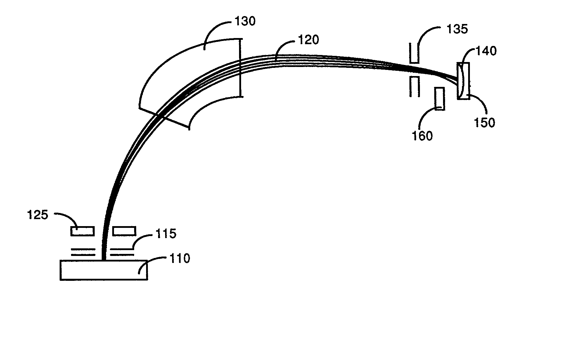
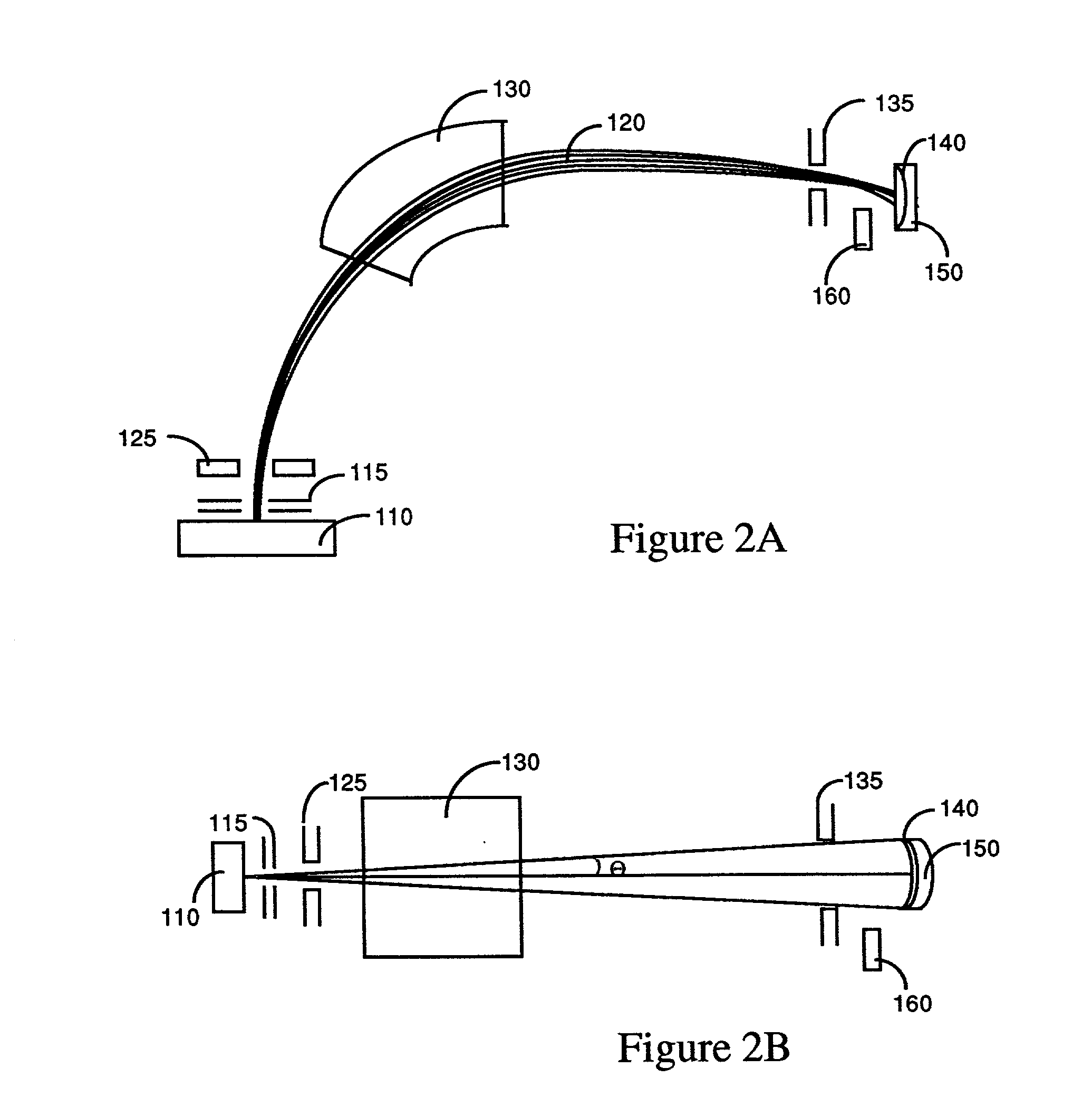
[0026] Referring to FIG. 2A for a top view of an ion implantation apparatus 100 according to the present invention. The implanting apparatus includes an ion beam source 110 with an extraction assembly 115, directing an ion beam 120 to project through a magnetic deflector 125. The ion beam 120 than travels through a mass analyzer, e.g., an ion mass selector 130 to impinge on a target substrate 140 mounted on a substrate holder 150. The ion beam source 110 of the implantation apparatus is housed in a vacuum chamber that can be evacuated by a vacuum...


PUM

PropertyMeasurementUnit
Angleaaaaaaaaaa
Diameteraaaaaaaaaa
Densityaaaaaaaaaa

Abstract

This invention discloses an ion implantation apparatus that has an ion source and an ion extraction means for extracting an ion beam therefrom. The ion implantation apparatus further includes an ion beam sweeping-and-deflecting means disposed immediately next to the ion extraction means. The ion implantation apparatus further includes a magnetic analyzer for guiding the ion beam passed through the deflecting-and-sweeping means. The mass analyzer is also used for selecting ions with specific mass-to-charge ratio to pass through a mass slit to project onto a substrate. The sweeping-and-deflecting means is applied to deflect the ion beam to project through the magnetic mass analyzer and the mass slit for sweeping the ion beam over a surface of the substrate to carry out an ion implantation. In a preferred embodiment, the ion implantation apparatus further includes a plasma electron flood system disposed between the mass slit and the substrate for projecting a plurality of electrons to the ion beam for preventing a space-charge and beam dispersion. In another preferred embodiment, the ion beam extraction and projecting system of this invention further includes a divergent ion-beam extracting optics for extracting an ion beam with a small divergent angle for projecting and diverging the ion beam as the ion beam is projected toward the target surface.

Description

[0001] 1. Field of the Invention[0002] The invention disclosed herein relates generally to apparatus for performing ion implantation employed in the manufacturing process of semiconductor and optical communication devices. Specifically, this invention relates to an improved implantation apparatus and methods for performing a high / medium current and low energy ion implantation.[0003] 2. Description of the Prior Art[0004] Ion implantation is a ballistic process used to introduce atoms or molecules, generally referred to as dopants, to make materials with useful properties. In particular, ion implantation is a common process used in making modern integrated circuits. Ion implantation process may also be applied for thin film deposition with controlled thickness and predefined surface properties employed for manufacturing optical or display devices. However, the semiconductor equipment suppliers are now faced with a difficult challenge to make a simple serial implantation machine capabl...

Claims


Application Information

Patent Timeline
IPC IPC(8): H01J37/317
CPCH01J2237/0041H01J37/3171
Inventor CHEN, JIONGWAN, ZHIMIN
Owner ADVANCED ION BEAM TECHNOLOGY INC
Why Eureka
Try Eureka